Measurement of Rate of Turn using Turn and Slip Indicator
The turn and slip indicator shows the rate of turn and indicates slip or skid during turns. It helps pilots maintain balanced flight by coordinating aileron and rudder inputs.
Introduction to the Turn and Slip Indicator
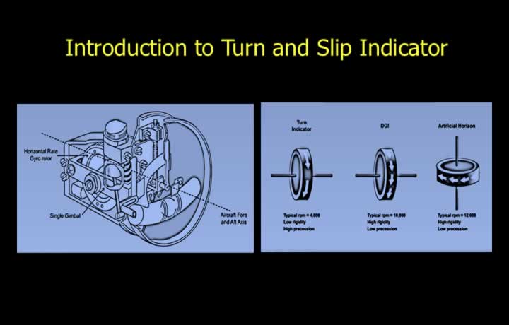
- The Turn and Slip Indicator consists of two components: a turn indicator and a slip indicator.
- The turn indicator uses a horizontal-axis rate gyro to measure the rate of turn.
- The horizontal rate gyro measures rotation about the aircraft’s vertical (yaw) axis.
- The gyro operates at a relatively low rotor speed to make use of the property of precession.
- A lower rotor RPM reduces rigidity and increases the rate of precession.
- The slip indicator is a pendulous device that indicates whether a turn is balanced.
- The Turn Coordinator is an improved version of the conventional Turn and Slip Indicator.
Construction of Rate of Turn Indicator
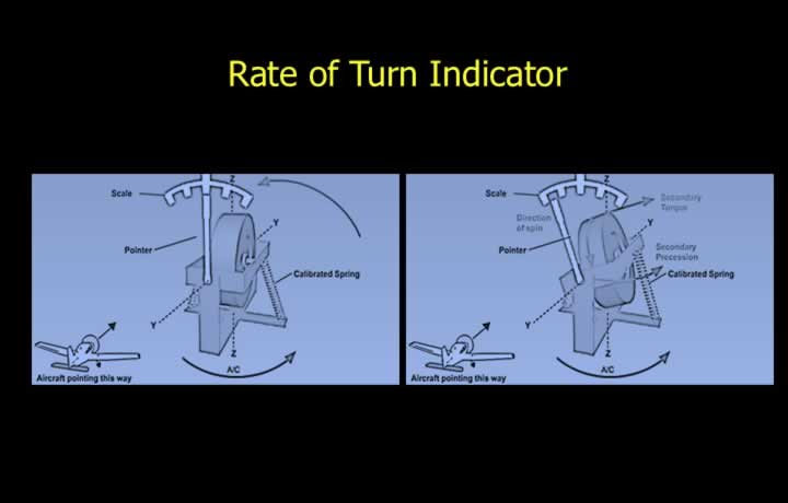
- The turn indicator contains a single-gimbal rate gyro with one degree of freedom.
- The gyro spin axis is aligned with the aircraft’s lateral (horizontal) axis.
- The gimbal is attached to the aircraft structure through calibrated springs.
- The gyro frame responds only to yawing motion and is unaffected by pure banking motion.
- During a turn, the applied torque produces gyroscopic precession until equilibrium is reached.
- At equilibrium, the spring tension is directly proportional to the aircraft’s rate of turn.
- The calibrated spring displacement is therefore used to indicate the rate of turn.
Failure Warning Device in TSI
- Changes in rotor speed produce inaccurate rate-of-turn indications.
- A reduction in rotor speed causes the instrument to indicate a higher-than-actual rate of turn.
- An increase in rotor speed causes the instrument to indicate a lower-than-actual rate of turn.
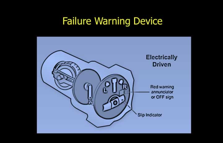
- Electrically driven turn indicators include a red warning flag to indicate electrical power failure.
- The instrument intentionally uses a lower rotor speed to increase gyroscopic precession.
- Lower rotor RPM reduces rigidity and improves the sensitivity of the rate gyro.
Slip Indicator
Principle of a Slip Indicator
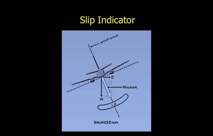
- The slip indicator shows whether the aircraft is making a balanced turn.
- It consists of a solid ball enclosed within a curved, liquid-filled transparent tube.
- The ball is subjected to the same centrifugal force acting on the aircraft.
- The ball experiences both gravitational force and centrifugal force.
- The vector sum of these forces produces the resultant force.
- During a balanced turn, the resultant force acts along the aircraft’s vertical axis.
- A balanced turn is indicated when the ball remains centred at the bottom of the tube.
Interpretation of the Slip Indicator
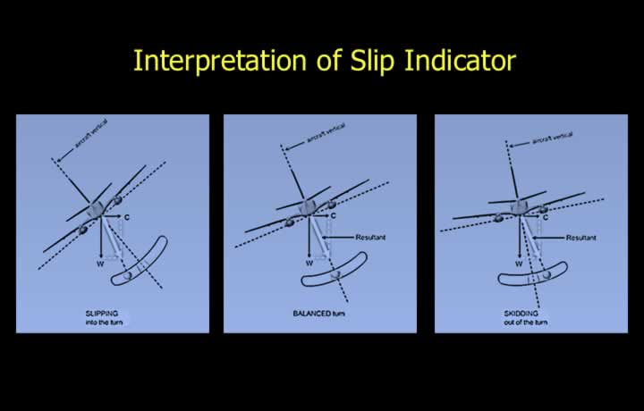
- The resultant force is the vector sum of gravity and centrifugal force.
- A centred ball indicates a balanced turn.
- In a balanced turn, the resultant force lies in the aircraft’s vertical plane.
- Insufficient bank (Skid):
- The ball moves toward the outside of the turn.
- The aircraft is said to be skidding.
- Excessive bank (Slip):
- The ball moves toward the inside of the turn.
- The aircraft is said to be slipping.
Turn Coordinator
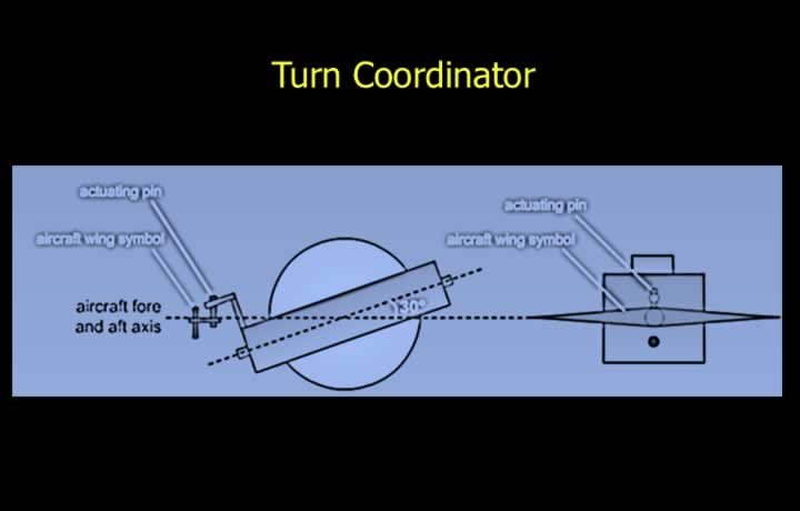
- The Turn Coordinator is designed primarily to indicate a Rate One Turn.
- A Rate One Turn is a turn of 180° per minute (or 360° in two minutes).
- The Turn Coordinator uses a rate gyro inclined approximately 30° to the aircraft’s longitudinal axis.
- Because of the inclined gyro, the instrument is sensitive to both roll and yaw.
- An actuating pin transfers gyro movement to the display, providing a faster response than a conventional Turn and Slip Indicator.