Direction Measurement using Gyro Magnetic Compass
A gyro-magnetic compass combines the stability of a gyroscope and accuracy of compass using the Earth’s magnetic field. It reduces errors caused by acceleration, turning and magnetic dip. This makes a GMC more reliable for maintaining precise heading during flight.
Introduction to the Gyro Magnetic Compass
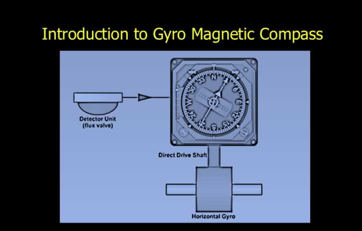
- A remote-indicating compass reduces many of the limitations of a direct-reading magnetic compass.
- It minimises heading errors that occur during aircraft acceleration and turns.
- It reduces magnetic deviation caused by locating the sensing element inside the cockpit.
- It allows magnetic heading information to be transmitted to other aircraft instruments.
- A gyro magnetic compass combines a directional gyro with a magnetic compass system.
- The directional gyro is continuously monitored and corrected by a magnetic detector.
- The gyro is corrected using a slow precession rate of approximately 3° per minute.
- The slow correction rate filters out temporary errors from the magnetic detector.
Construction of the Gyro Magnetic Compass
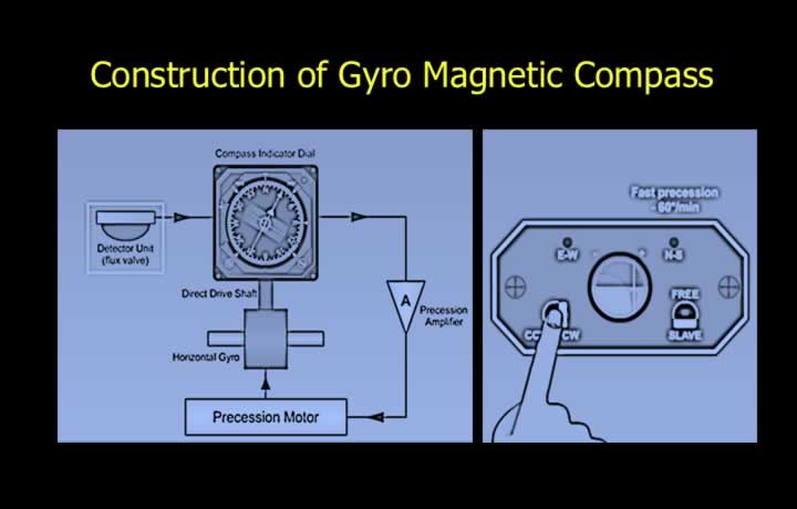
- The Gyro Magnetic Compass is also known as the Magnetic Heading Reference System (MHRS).
- It combines the stability of a gyroscope with the directional reference of a magnetic compass.
- The system consists of a horizontal directional gyro and a magnetic flux valve detector.
- A compass dial displays heading through a precession amplifier and drive motor.
- Both manual and automatic rapid synchronisation systems are provided.
- A rapid synchronisation button quickly aligns the directional gyro with the magnetic flux valve.
Magnetic Flux Valve
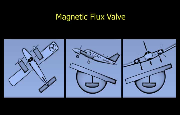
- The magnetic flux valve senses the direction of magnetic north.
- A three-spoke flux valve is usually installed beneath a wing tip or inside the tail fin.
- This location minimises interference from electrical equipment.
- The flux valve is suspended pendulously using a Hooke’s joint.
- The Hooke’s joint allows the detector to remain level during aircraft pitch and roll.
Magnetic Flux Detector
Principle of the Magnetic Flux Valve
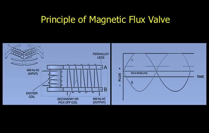
- The magnetic flux valve operates on Faraday’s Law of Electromagnetic Induction.
- An electromotive force (EMF) is induced whenever the magnetic flux linking a conductor changes.
- The induced EMF is proportional to the rate of change of magnetic flux.
- The detector consists of a central excitation coil surrounded by three sensing spokes.
- Alternating current in the central coil creates equal magnetic fields in the surrounding spokes.
- Without an external magnetic field, the resulting output is zero.
- The Earth’s magnetic field changes the magnetic saturation of the spokes.
- This produces an output voltage proportional to the direction of magnetic north.
Transmission of Magnetic Heading
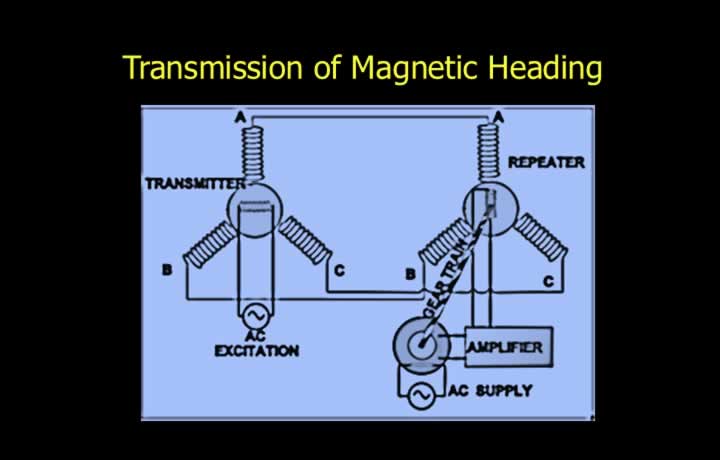
- A Selsyn (Synchro) system transmits heading information between transmitting and receiving units.
- The transmitter rotor rotates with the heading drive shaft.
- The rotor position represents the aircraft heading.
- The rotor induces an equivalent magnetic field in the stator windings.
- The receiving synchro develops currents that rotate its shaft to the same position.
- An error signal exists whenever the transmitter and receiver are not aligned.
- The repeater continues rotating until the error voltage becomes zero, indicating the correct heading.
Signal Processing to the Compass Dial
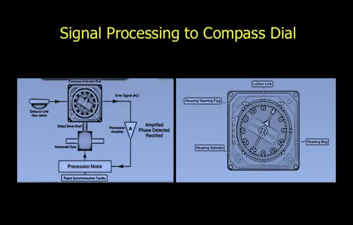
- The Selsyn system produces an error signal whenever the displayed heading is incorrect.
- The error signal is amplified, phase detected, and converted into direct current (DC).
- The DC output drives the precession motor that rotates the compass dial.
- The displayed heading is the directional gyro heading corrected by the magnetic flux valve.
- The compass card is read against a fixed lubber line.
- A heading bug allows the pilot to preset a desired heading.
- A warning flag indicates failure of the magnetic flux detector or associated circuitry.
Control Panel of the Gyro Magnetic Compass
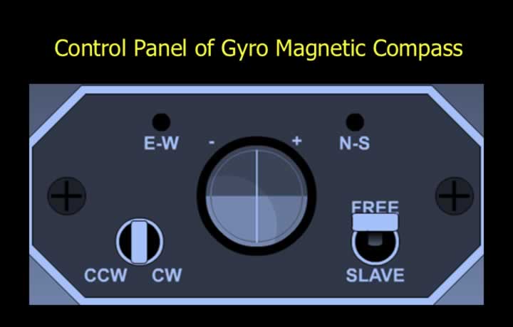
- A FREE/SLAVE selector chooses between gyro-only and magnetically slaved operation.
- Slave Mode is the normal operating mode.
- In Slave Mode, the directional gyro is continuously corrected by the magnetic flux valve.
- An annunciator indicates that magnetic slaving is operating.
- Free Mode displays gyro heading without magnetic correction.
- Free Mode is commonly used near the magnetic poles where magnetic dip is excessive.
- CW and CCW controls are provided to manually synchronise the initial heading.
Gyro Wander
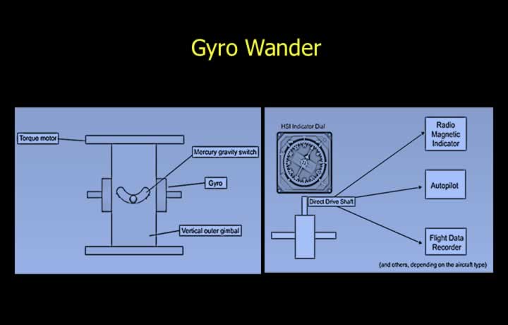
- Gyro wander consists of gyro drift and gyro topple.
- Drift is minimised by continuously slaving the directional gyro to the magnetic flux valve.
- Topple is corrected using mercury levelling switches and torque motors.
- These correction systems slowly precess the gyro back to the horizontal reference.
- The slow precession rate prevents unnecessary corrections caused by temporary disturbances.
- Temporary disturbances include aircraft turns and acceleration errors.
- The Selsyn (Synchro) system also distributes heading information to instruments such as the Radio Magnetic Indicator (RMI), Horizontal Situation Indicator (HSI), and Autopilot.