Inertial Navigation System (INS)
The Inertial Navigation System (INS) is used to determine an aircraft’s position, speed, and direction without relying on external navigation aids. It provides accurate navigation by using gyroscopes and accelerometers to continuously track the aircraft’s movement.
Introduction to Inertial Navigation Systems
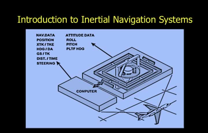
- The Inertial Navigation System (INS) is a highly accurate self-contained navigation system.
- It operates independently of any ground-based navigation aid.
- The INS is capable of worldwide navigation.
- It is an advanced form of dead reckoning that continuously calculates aircraft position.
- An INS consists of three main units:
- Inertial Navigation Unit (INU)
- Mode Selector Unit (MSU)
- Control and Display Unit (CDU)
Principle of Inertial Navigation Systems
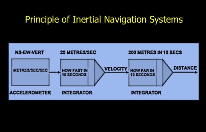
- Accelerometers and integrators form the core of an Inertial Navigation System.
- Precision accelerometers measure aircraft acceleration and deceleration.
- First-stage integrators convert acceleration into velocity.
- Second-stage integrators convert velocity into distance travelled.
- The INS continuously computes movement in the North-South and East-West directions.
- The aircraft’s new position is determined from the calculated distances travelled.
Principle of Accelerometers
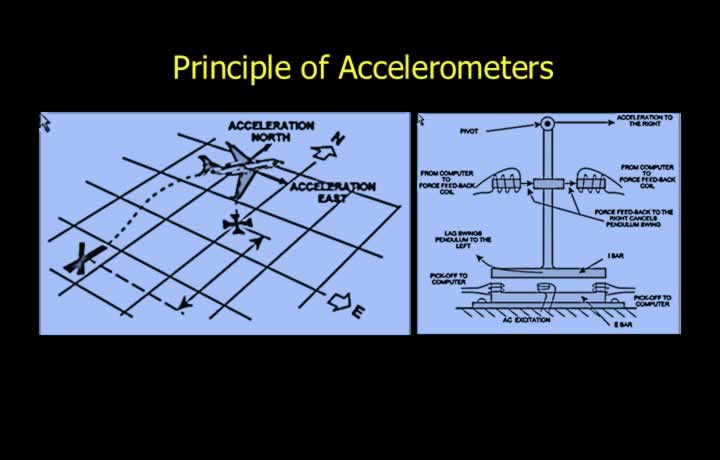
- Accelerometers measure the linear acceleration of the aircraft.
- An E-I bar pendulous suspension forms the sensing element.
- The E-I bar is manufactured from materials having high magnetic permeability.
- Aircraft acceleration causes the pendulum to move away from its null position because of inertia.
- The E-I bar detects this movement by measuring changes in magnetic flux.
- The resulting signal is sent to a pick-off device.
- The signal is amplified and supplied to a torque motor.
- The torque motor restores the pendulum to its null position.
- The restoring current is directly proportional to the aircraft acceleration.
First-Stage Integrators
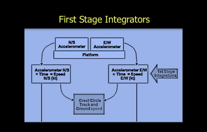
- Integrators multiply a measured quantity by time.
- The first-stage integrator converts acceleration into velocity.
- North-South acceleration is integrated to obtain North-South velocity.
- East-West acceleration is integrated to obtain East-West velocity.
- These velocity components are subsequently used to determine distance travelled.
Second-Stage Integrators
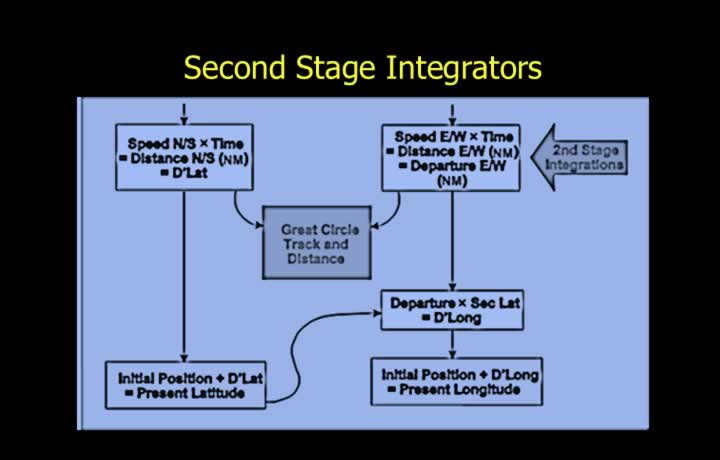
- The second-stage integrator converts velocity into distance.
- North-South velocity is integrated to obtain North-South distance travelled.
- East-West velocity is integrated to obtain East-West distance travelled.
- The calculated distances determine the aircraft’s new position.
Calculation of New Latitude and Longitude
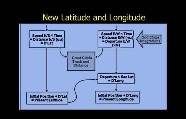
- Latitude is calculated by adding or subtracting the distance travelled north or south.
- Assuming the Earth is a perfect sphere, one minute of latitude equals one nautical mile.
- Longitude is determined using the calculated departure.
- Departure is the distance travelled along a parallel of latitude.
- The change in longitude is obtained by multiplying departure by the secant of latitude.
- A secant multiplier is therefore required to calculate longitude accurately.
- Accurate latitude information is essential for correct longitude calculation.
Stabilisation of INS Platform
Platform Stabilisation of INS
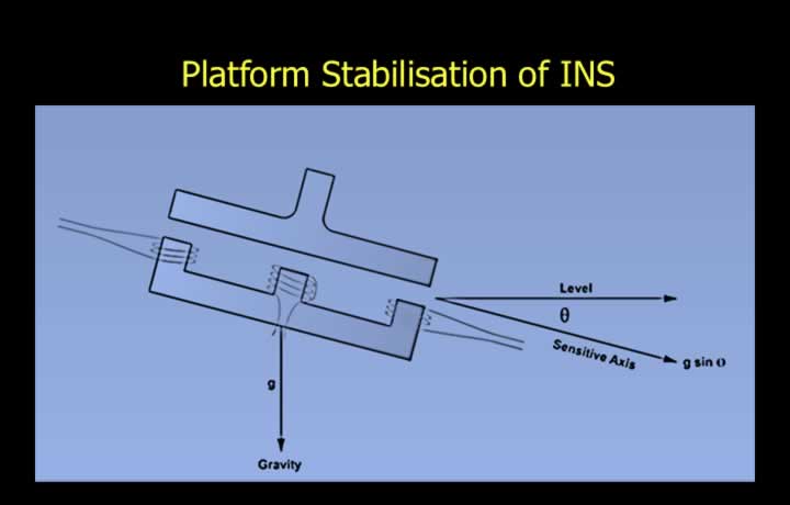
- Accelerometers require a stabilised platform for accurate measurements.
- A tilted platform causes incorrect acceleration measurements.
- The accelerometers are mounted on a gyro-stabilised platform.
- The platform remains level during aircraft pitch, roll, and yaw.
- This stabilisation keeps the accelerometers horizontal with respect to the Earth’s surface.
Construction of the Stabilised Platform
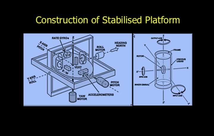
- The stabilised platform contains three horizontal-axis gyroscopes.
- The spin axes of the gyroscopes are mutually perpendicular.
- Each gyro has one degree of freedom and is connected to a control motor.
- Rate-integrating space gyros are used.
- The gimbals resemble sealed cans floating within one another.
- Viscous fluid minimises bearing friction.
- The gyros effectively provide two degrees of freedom.
- The accelerometers remain horizontal to the Earth’s surface.
- The stabilised platform also compensates for Earth-rate and transport wander.
Inaccuracy in Position Fix due to Gyro Wander
Correction for Gyro Wander
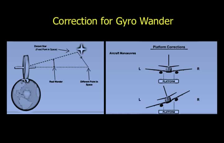
- Both real and apparent gyro wander must be corrected.
- Gyro wander consists of drift and topple.
- Real wander results from manufacturing imperfections.
- High-quality gyros greatly reduce real drift.
- Platform stabilisation compensates for aircraft manoeuvres.
- Apparent drift and topple must also be corrected.
- Earth rate and transport wander are the primary causes of apparent wander.
Earth-Rate Correction
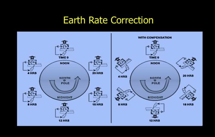
- The stabilised platform must remain horizontal relative to the Earth’s surface.
- Computed Earth-rate corrections are applied through a feedback system.
- The feedback system continuously drives the stabilisation platform.
- Earth-rate correction consists of two components:
- Horizontal Component = 15 × sin(Latitude) (degrees per hour)
- Vertical Component = 15 × cos(Latitude) (degrees per hour)
- These corrections maintain accurate platform alignment.
Transport Wander Correction
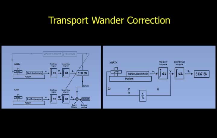
- Transport wander occurs because the aircraft moves over the Earth’s surface.
- The horizontal component is:
Horizontal Transport Wander = (Easterly Velocity ÷ 60) × tan(Latitude)
- The vertical component is corrected through an electromechanical feedback loop.
- The North-South velocity component is divided by the Earth’s radius.
- Schuler tuning provides correction of the vertical component.
Coriolis Force and Centripetal Acceleration
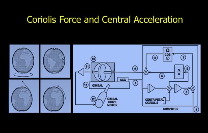
- The INS computer continuously corrects for Coriolis and centripetal acceleration.
- Coriolis acceleration results from aircraft motion over the rotating Earth.
- Centripetal acceleration results from motion along the Earth’s curved surface.
Start-Up Sequence of Inertial Navigation System
Caging (Warm-Up)
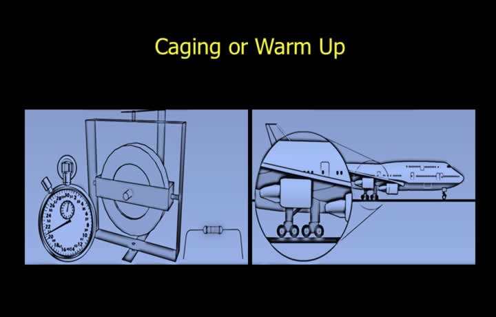
- Initial INS alignment consists of caging, levelling, and gyro compassing.
- Caging (warm-up) is the first stage and typically lasts about 3 minutes.
- The frame and both gimbals are positioned at right angles.
- Fluid-filled components are heated to their operating temperature.
Coarse and Fine Levelling
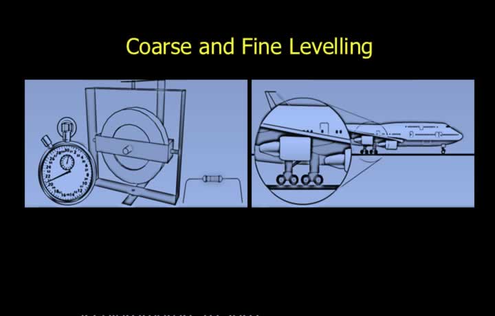
- Levelling follows caging and typically lasts about 3 minutes.
- The accelerometers are adjusted until they sense zero horizontal acceleration.
- The platform is aligned horizontally while the aircraft remains stationary.
- The local gravity vector provides the reference.
- A feedback system drives the levelling motors.
- Coarse levelling aligns the platform within approximately 1–2°.
- Gravity switches and horizontal accelerometers provide correction signals.
- Fine levelling improves the alignment to approximately 6 seconds of arc.
Gyro Compassing
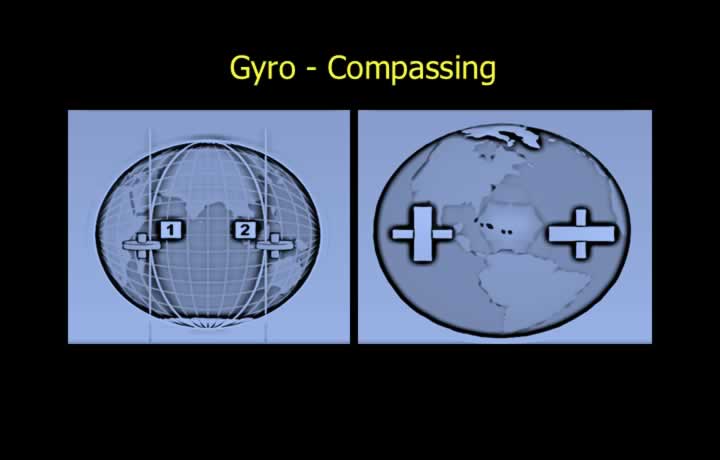
- Gyro compassing is the final alignment stage and lasts approximately 11 minutes.
- The system senses the Earth’s rotation and aligns itself with True North.
- Earth rate provides the necessary reference information.
- Gyro compassing becomes unreliable above approximately 70° latitude.
- The reduced Earth-rate component at high latitudes limits accuracy.
- Correct azimuth alignment produces zero east-west acceleration.
- The platform rotates with the Earth’s east-west motion.
- Initial alignment is sensitive to incorrect latitude entry.
- Incorrect longitude entry does not significantly affect alignment.
Errors in INS Systems
Schuler Period
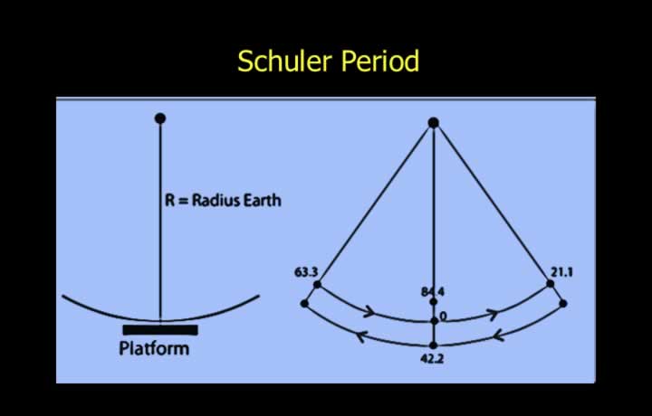
- Imagine a pendulum whose length equals the Earth’s radius.
- The pendulum bob remains directed toward the Earth’s centre.
- If the suspension point moves along the Earth’s surface, the pendulum remains vertical.
- A stabilised platform behaves similarly, remaining horizontal to the Earth’s surface.
Schuler Oscillations
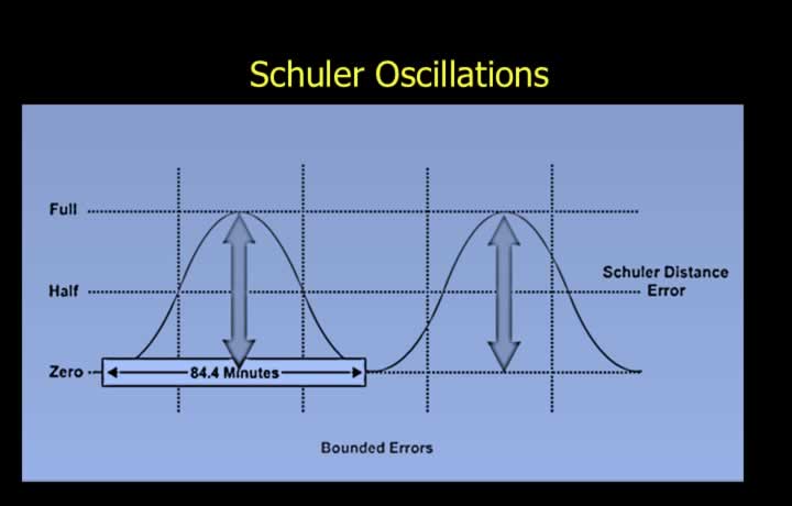
- If the pendulum is displaced, it oscillates with the Schuler Period.
- The Schuler Period is approximately 84.4 minutes.
- These oscillations produce cyclic navigation errors.
- The calculated aircraft position oscillates between minimum and maximum error every 84.4 minutes.
Bounded Errors
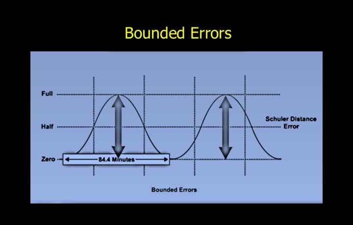
- Bounded errors increase and decrease during each Schuler cycle.
- One complete Schuler cycle lasts 84.4 minutes.
- Typical causes include:
- Initial platform tilt.
- Accelerometer measurement errors.
- First-stage integrator errors.
- These errors do not continuously increase but oscillate about the true position.
Unbounded (Ramp) Errors
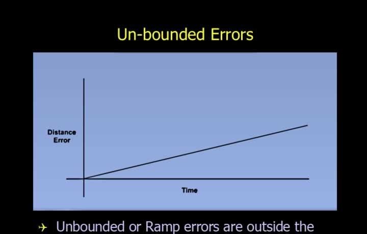
- Unbounded errors lie outside the feedback control loop.
- These errors increase continuously with time.
- Typical causes include:
- Initial azimuth misalignment during gyro compassing.
- Real drift of the azimuth gyro.
- Gyro topple.
- Second-stage distance integrator errors.
- Typical acceptable values are:
- Azimuth misalignment: within 0.1°.
- Gyro drift: approximately 0.01°.
- Gyro topple: approximately 0.01°.
Cumulative Errors
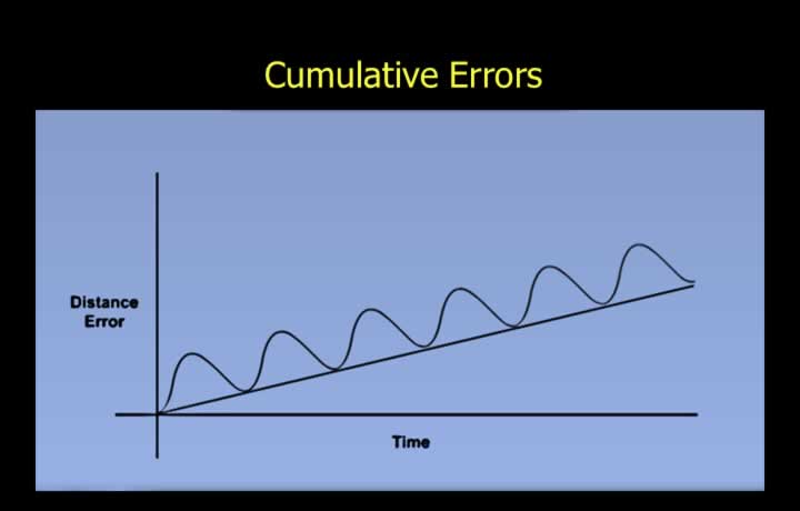
- An Inertial Navigation System experiences both bounded and unbounded errors.
- Additional errors arise from simplifying assumptions such as treating the Earth as a perfect sphere.
- The combined error follows an increasing sinusoidal pattern with time and distance flown.
- Improved manufacturing techniques significantly reduce these errors.
- Modern Ring Laser Gyroscopes (RLGs) have greatly improved INS accuracy by reducing mechanical errors.