
Display of Instruments using Head-Up Display (HUD)
The Head-Up Display (HUD) projects essential flight information onto a transparent screen in the pilot’s forward line of sight. It allows pilots to monitor flight data without looking down at the instrument panel, improving situational awareness and safety, especially during take-off and landing.
Components of Head-Up Display
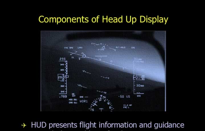
- A Head-Up Display (HUD) presents flight information within the pilot’s forward line of sight.
- It is especially useful during critical phases of flight such as take-off and landing.
- The HUD system consists of the following main components:
- Display Controller – selects and controls display modes.
- Display Guidance Computer – generates symbology and flight guidance data.
- Overhead Unit – acts as the projector system.
- Combiner – a semi-reflective glass that displays images to the pilot.
- Ambient Light Sensor – adjusts brightness based on cockpit lighting conditions.
- Display brightness is automatically adjusted according to external and cockpit lighting conditions.
Eye Box
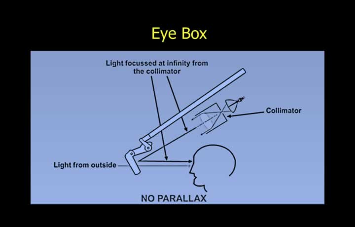
- The overhead unit uses a collimator to produce parallel light rays.
- The collimated image is projected toward an eye reference point.
- The eye reference point represents the ideal viewing position for the pilot.
- The image is designed to appear at optical infinity to reduce eye strain.
- Parallax error is minimised through correct optical alignment.
- The eye box (or head motion box) defines the allowable range of pilot head movement.
- The HUD remains visible within a 3D volume around the eye reference point.
- Typical eye box dimensions are approximately 5 inches wide, 3 inches high, and 6 inches deep.
Bore-sighting
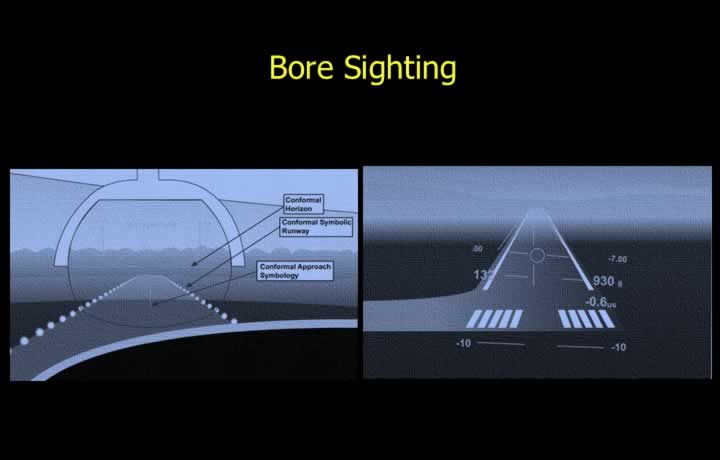
- Bore-sighting ensures the HUD produces a conformal display.
- Conformal display alignment prevents disorientation during visual transition.
- The real-world view and HUD symbology must align accurately.
- Bore-sighting ensures correct scaling, positioning, and perspective of displayed symbols.
- The process aligns virtual symbols with real-world objects within acceptable tolerance.
- The allowable mismatch between image and object is typically less than 0.5°.
Advancements in Head-Up Displays
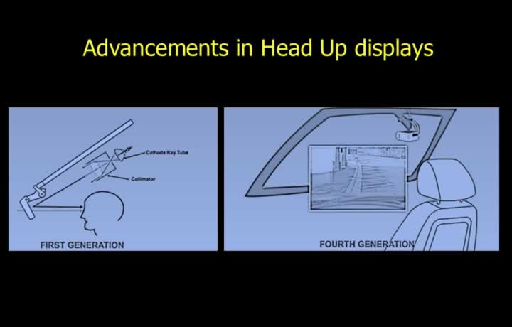
- First-generation HUDs used cathode ray tube (CRT) projectors and optical combiners.
- These systems suffered from high voltage requirements and image fading issues.
- Second-generation HUDs introduced solid-state light sources.
- They offered improved brightness, wider field of view, and sharper imagery.
- Third-generation HUDs introduced optical waveguide technology instead of overhead projection systems.
- The eye box size was significantly increased for better pilot flexibility.
- Modern systems may use phosphor-coated wind-shields instead of separate combiners.
- Fourth-generation HUDs can project directly onto the windscreen, eliminating separate display glass.
Information in Head Up Display
Mandatory Information
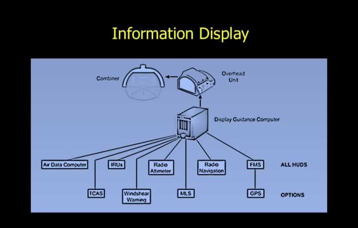
- Air Data Computer (ADC) parameters
- Inertial Reference Unit (IRU) data
- Radio Altimeter readings
- Radio Navigation information
- Flight Management System (FMS) guidance
Optional Information
- Terrain Awareness and Warning System (TAWS)
- Wind Shear Warning alerts
- Microwave Landing System (MLS) guidance
- Global Positioning System (GPS) data
Operating Modes of Head Up Display
Conformal Mode
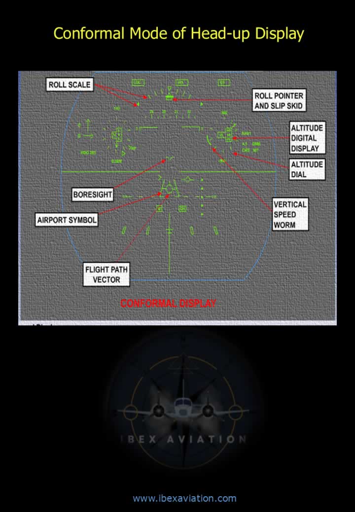
- In conformal mode, HUD symbology aligns directly with real-world objects.
- This improves situational awareness during flight operations.
Runway Approach Mode
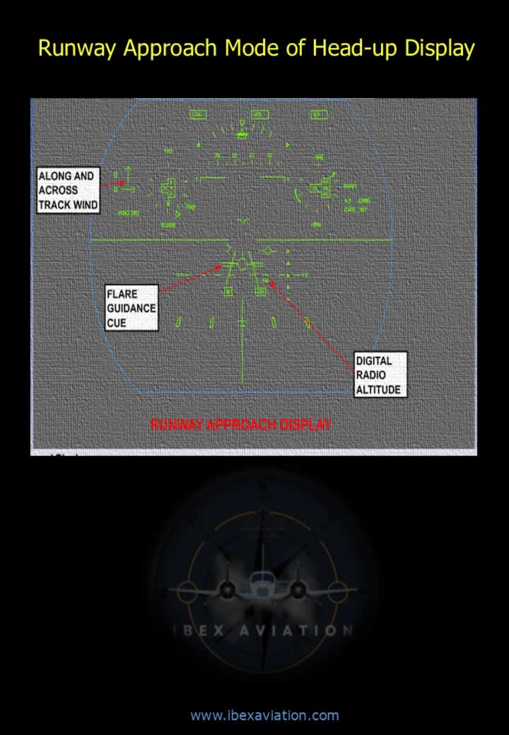
- Provides guidance cues during final approach and landing.
- Ensures correct glide path and alignment with runway centreline.
En-Route Mode
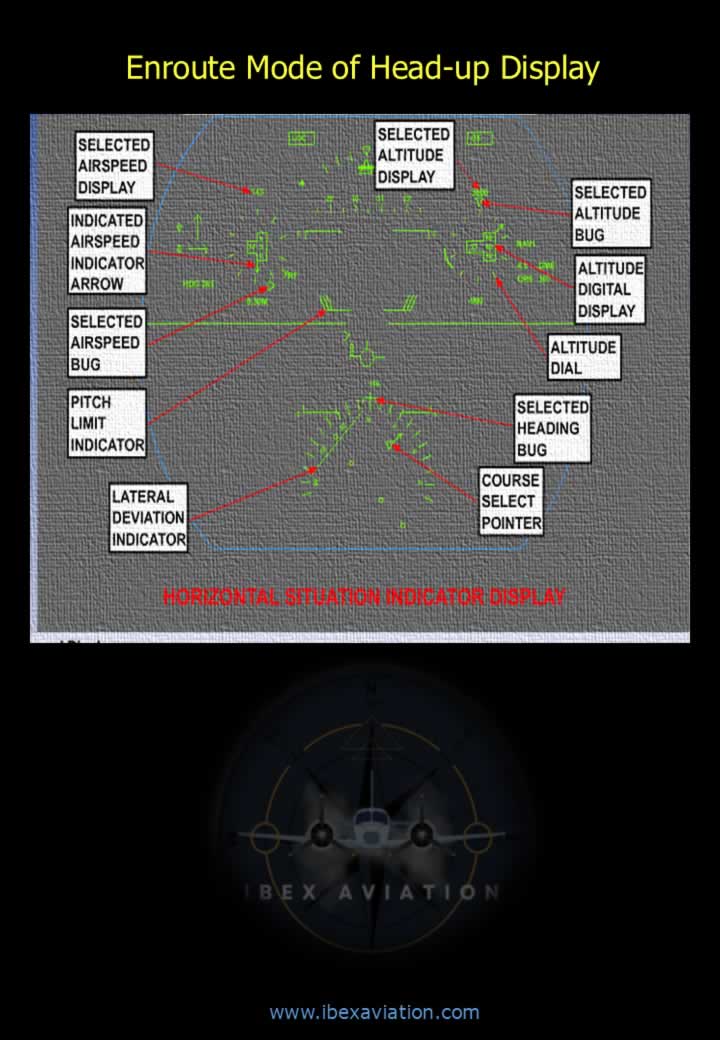
- Displays navigation and flight path information during cruise phase.
- Optimised for long-duration flight guidance.
Drawback of Head Up Display (HUD)
HUD Tunnelling Effect
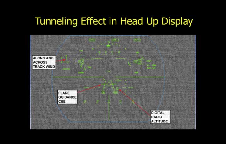
- The tunnelling effect occurs when pilots become overly focused on HUD information.
- This can lead to reduced attention to external visual cues.
- It may negatively impact situational awareness.
Cluttering in HUD
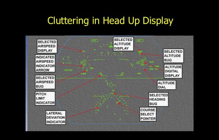
- HUD clutter refers to excessive or dense symbology on the display.
- Clutter can obscure important visual cues from the outside environment.
- This may lead to pilot confusion or increased workload.
Enhanced Vision System (EVS)
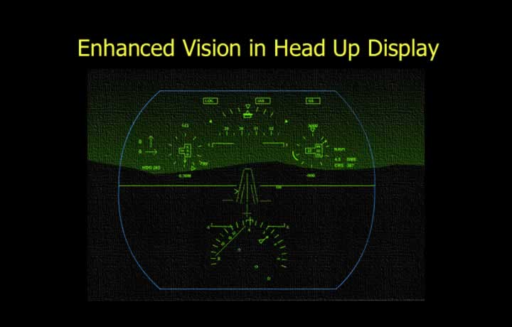
- Enhanced Vision Systems assist pilots during low-visibility operations and night flying.
- Forward Looking Infrared (FLIR) technology generates thermal imagery of the environment.
- This improves terrain and obstacle detection in darkness or poor weather conditions.
Synthetic Vision System (SVS)
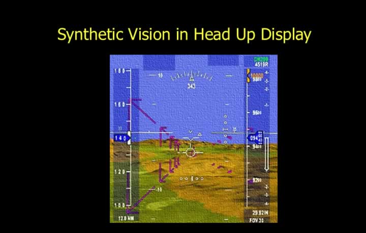
- Synthetic Vision Systems generate a computer-created 3D representation of terrain.
- They are particularly useful during Instrument Meteorological Conditions (IMC).
- SVS enhances situational awareness by displaying terrain, obstacles, and flight paths.