
Plotting on Charts – Lambert vs Mercator
Lambert Projection maintains accurate angles and is suitable for long-distance flight planning. Mercator Projection preserves direction and is mainly used for navigation over equatorial regions.
Lambert’s Plotting – Find Magnetic Bearing
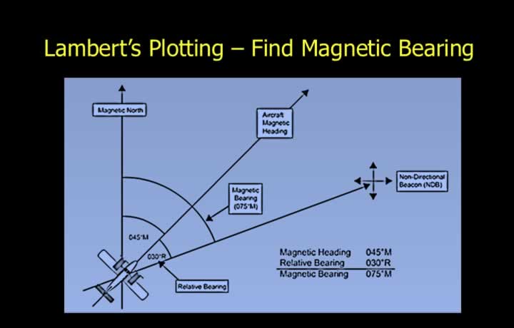
- Convert relative bearings to magnetic bearings.
- Magnetic Bearing = Relative Bearing + Magnetic Heading
- Subtract 360° if the value exceeds 360°.
- Convert magnetic bearings to the station into magnetic bearings from the station.
- Convert QDM to QDR.
- Add or subtract 180°.
Lambert’s Plotting – Find True Bearing
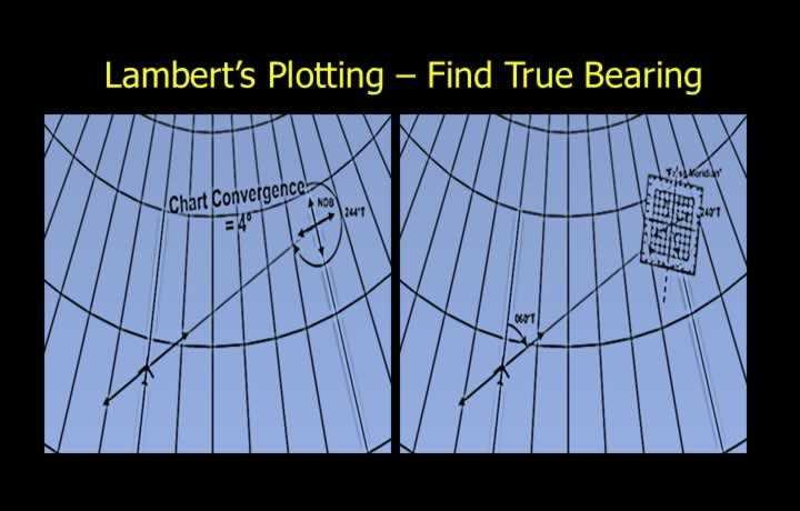
Relative Bearing to True Bearing Conversion
- True Bearing = Relative Bearing + True Heading
- Subtract 360° if the value exceeds 360°.
True Bearing from ADF and VOR
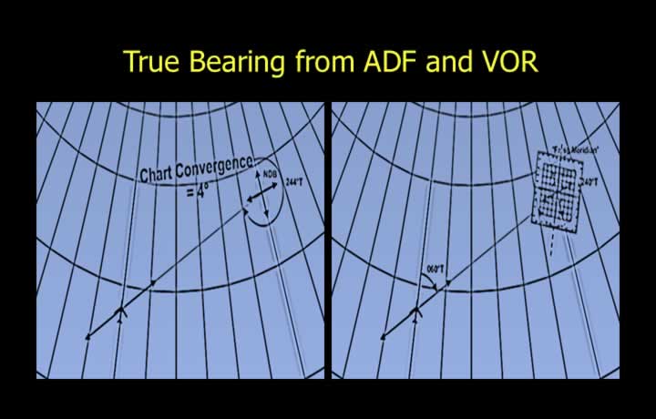
- If the bearing is measured at the ground station (e.g., VOR):
- Apply the station variation to the magnetic bearing to obtain the true bearing.
- If the bearing is measured at the aircraft (e.g., ADF):
- Apply the aircraft variation to the magnetic bearing to obtain the true bearing.
- Find the reciprocal bearing from the station.
Lambert’s Plotting – Apply Chart Convergence
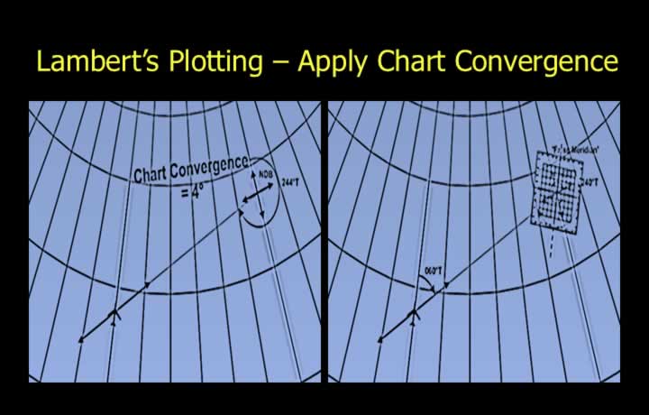
- Obtain the bearing to plot by applying chart convergence.
- Plot from the false meridian at the ground station.
- Alternatively, calculate the chart convergence and then plot.
Mercator Plotting

- The lateral direction of radio signals from VDF, VOR, and NDB follows the great-circle path (the shortest path).
- On Mercator charts:
- Rhumb lines are straight lines.
- Great circles are curved and concave toward the equator.
- Measured great-circle bearings must be converted into rhumb-line directions before plotting on a Mercator chart.
Calculation of Bearing to Plot on Mercator

- Apply the conversion angle (½ convergence) at the point where the bearing is measured to convert from a Great Circle (GC) to a Rhumb Line (RL).
- For VOR and VDF (bearings measured at the station):
- Apply the station variation and the conversion angle at the station.
- For ADF and AWR (bearings measured at the aircraft):
- Apply the aircraft variation and the conversion angle at the aircraft.
- Plot the reciprocal bearing from the ground station.