
Inertial Reference System (IRS)
The Inertial Reference System (IRS) provides accurate attitude, heading, and motion data but does not independently compute navigation position. In modern aircraft, the IRS supplies reference data to the Flight Management System (FMS), which performs navigation calculations.
Introduction to the Inertial Reference System

- The Inertial Reference System (IRS) is a self-contained navigation system that provides highly accurate aircraft position and attitude information.
- Modern IRS units use Ring Laser Gyroscopes (RLGs) and high-performance digital computers.
- The system measures acceleration and angular motion about the aircraft’s pitch, roll, and yaw axes.
- Unlike a conventional Inertial Navigation System (INS), which measures movement in the North-South and East-West directions, the IRS performs mathematical coordinate transformation.
- The IRS is a strap-down system.
- The gyroscopes and accelerometers are rigidly mounted to the aircraft structure.
- Eliminating gimbals and moving parts improves reliability, accuracy, and maintainability.
Ring Laser Gyroscope
Sagnac Effect

- The Ring Laser Gyroscope operates on the Sagnac Effect.
- Two laser beams travel in opposite directions around a closed optical path.
- The starting and ending points are effectively located opposite each other within the optical cavity.
- If the gyro is stationary, both laser beams travel identical path lengths.
- When the gyro rotates, one beam travels a slightly longer path while the other travels a shorter path.
- This difference produces a measurable frequency shift between the two beams.
- The frequency difference is directly proportional to the angular rate of rotation.
- Although the theoretical explanation often uses a circular path, practical Ring Laser Gyros normally use a triangular optical cavity.
Construction of the Ring Laser Gyroscope
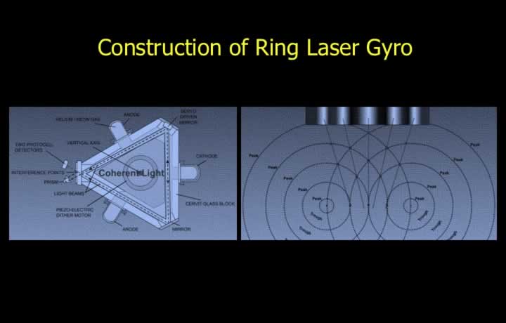
- A laser produces coherent light of a single frequency.
- A gas discharge between the cathode and anodes generates the laser beam.
- The laser beam is split into two beams.
- One beam travels clockwise while the other travels counter-clockwise around the optical cavity.
- The beams recombine at a photoelectric detector.
- The resulting interference pattern is used to determine the aircraft’s angular movement.
Laser Lock
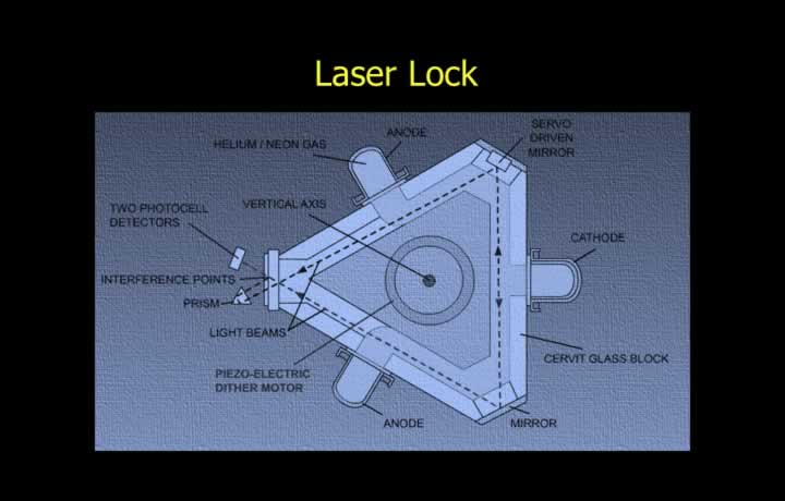
- Laser lock is a condition in which the Ring Laser Gyroscope incorrectly produces zero output.
- The error occurs because the two counter-propagating laser beams become synchronised.
- Laser lock generally occurs during very low angular rates.
- A technique called dithering is used to prevent laser lock.
- A piezoelectric dither motor continuously vibrates the gyro at a very small amplitude.
- This vibration prevents the laser beams from becoming synchronised.
Calculation of Position by a Combination of IRS and FMS
Axis Transformation
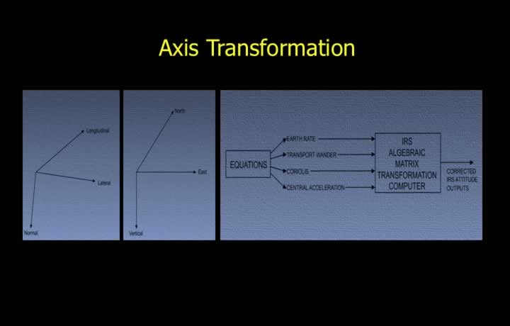
- Axis transformation converts aircraft-axis measurements into Earth-reference coordinates.
- The IRS accelerometers measure acceleration along the aircraft’s pitch, roll, and yaw axes.
- Unlike the INS, acceleration is not measured directly in the North-South and East-West directions.
- Matrix algebra is used to transform aircraft-axis measurements into Earth-axis components.
- The resulting motion is resolved into North-South, East-West, and vertical directions.
- The transformation computer also applies corrections to gyro outputs.
- A mathematical Earth model compensates for several predictable errors, including:
- Earth rate
- Transport wander
- Coriolis acceleration
- Centripetal (central) acceleration
- Schuler tuning
Initial Trihedron
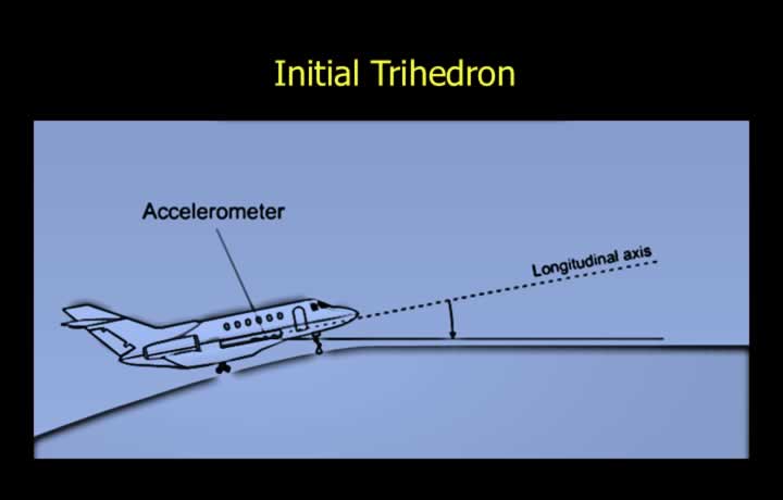
- During initialisation, the IRS is aligned with the aircraft rather than directly with the Earth’s surface.
- This differs from a conventional INS, where the platform is levelled horizontally to the Earth.
- The IRS computer detects the slope of the parking surface and any lateral aircraft tilt.
- These computed values are used to determine accurate heading corrections.
- The Earth’s rotation rate provides the reference for true heading alignment.
Inputs and Outputs of Inertial Reference System
Inputs to the IRS
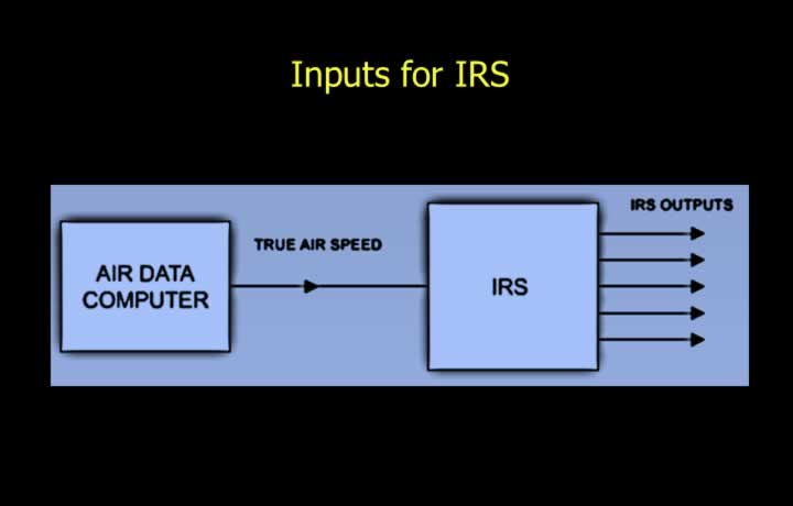
- The Inertial Reference System receives inputs from the following sensors:
- Three Ring Laser Gyroscopes.
- Two horizontal accelerometers aligned with the X and Y axes.
- One vertical accelerometer aligned with the Z axis.
- True Airspeed (TAS) information from the Air Data Computer (ADC).
Outputs of the IRS
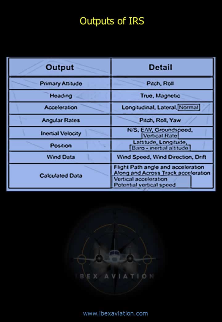
- The IRS supplies navigation and attitude information to multiple aircraft systems.
- Typical outputs include:
- Aircraft position (Latitude and Longitude).
- True heading.
- Magnetic heading (when combined with magnetic reference data).
- Pitch and roll attitude.
- Ground speed.
- Track angle.
- Wind speed and wind direction.
- Vertical speed.
- Acceleration data.
- Navigation information for the Flight Management System (FMS), Autopilot, Electronic Flight Instrument System (EFIS), and other avionics.
Kalman Filtering for the Flight Management System (FMS)
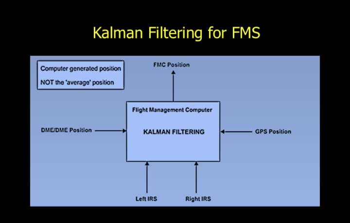
- The IRS provides one of the primary position inputs to the Flight Management System (FMS).
- The FMS continuously computes the aircraft’s deduced-reckoning position.
- The FMS does not simply average the positions from different navigation systems.
- Instead, it uses a mathematical algorithm known as Kalman Filtering.
- Kalman Filtering combines information from multiple navigation sources to determine the Most Probable Position (MPP).
- Typical navigation inputs include:
- Inertial Reference System (IRS).
- Global Positioning System (GPS).
- DME/DME Position Fixes.