Direction measurement using Directional Gyro Indicator (DGI)
A DGI (Directional Gyro Indicator) is an aircraft instrument that shows the aircraft’s heading using a gyroscope, independent of magnetic compass errors. It provides stable directional reference, helping pilots maintain accurate heading during turns, turbulence, and acceleration.
Introduction to Directional Gyro Indicator
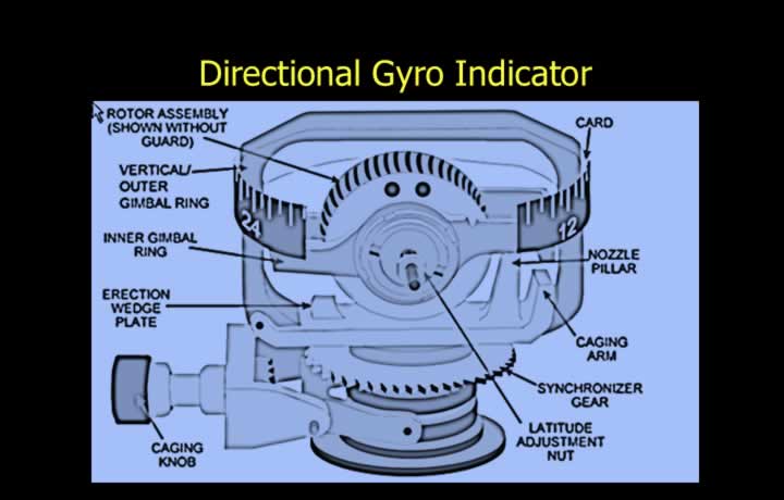
- DGI provides heading using a tied gyro with two degrees of freedom.
- Spin axis of the gyro is maintained in the yawing plane of the aircraft.
- Gyro motor is located in the inner gimbal, while readings are seen on the outer gimbal.
- Outer gimbal can rotate through 360°.
- Rotor axis, inner gimbal, and outer gimbal are at right angles to each other.
- In an air-driven DGI, an engine-driven pump provides an air jet to spin the rotor.
- The outer gimbal turns whereas the spin axis remains at its original position.
- The readings on the outer gimbal display the heading on a lubber line.
Self Adjustment of DGI
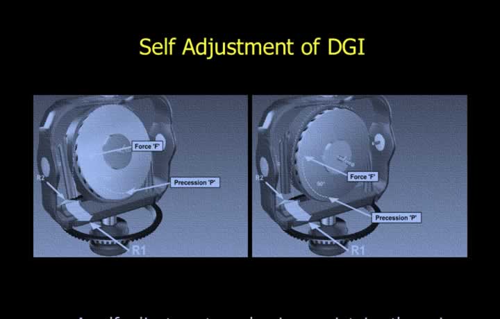
- A self-adjustment mechanism maintains the spin axis in the yawing plane.
- The self-adjustment is carried out in two distinct steps.
- Coarse adjustment takes place when a fresh air jet strikes the rotor at an angle.
- This fresh air creates an additional component of force.
- This force acts at 90° to the point of application.
- As a result, the spin axis is brought back to its original position.
- Fine adjustment is done by using a wedge plate.
- The wedge plate separates the used air jet from the rotor unequally.
- This causes the rotor to return to its original position.
Caging Knob of DGI
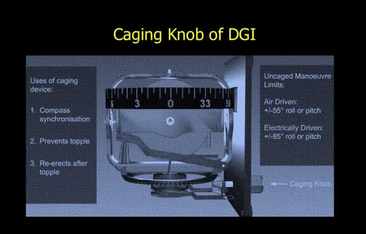
- A spring-loaded caging knob is provided to prevent topple locking mechanism.
- This spring-loaded switch can also re-erect a toppled gyro.
- The button can manually synchronize the gyro with the compass heading.
Limitations of an Un-caged DGI
- Air-driven gyro is limited to 55° pitch and roll.
- Electrically driven gyro is limited to 85° pitch and roll.
Gimballing Error
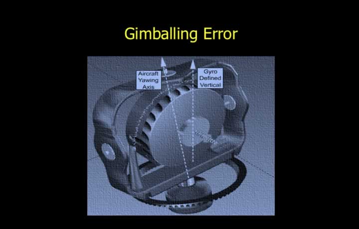
- Gimballing error is caused when the aircraft applies bank to turn.
- Error is caused if the outer gimbal moves to keep the spin axis steady.
- Pitching movement during bank aggravates this error.
- Maximum error is seen during bank while climbing or descending.
- In a 360° turn, this error varies with direction.
- Zero error is seen in four directions which are 90° apart.
- Gimballing error disappears when the aircraft levels out.
Calculation of Real and Apparent Drift while using Directional Gyro Indicator
Real Drift due to Mechanical Imperfections
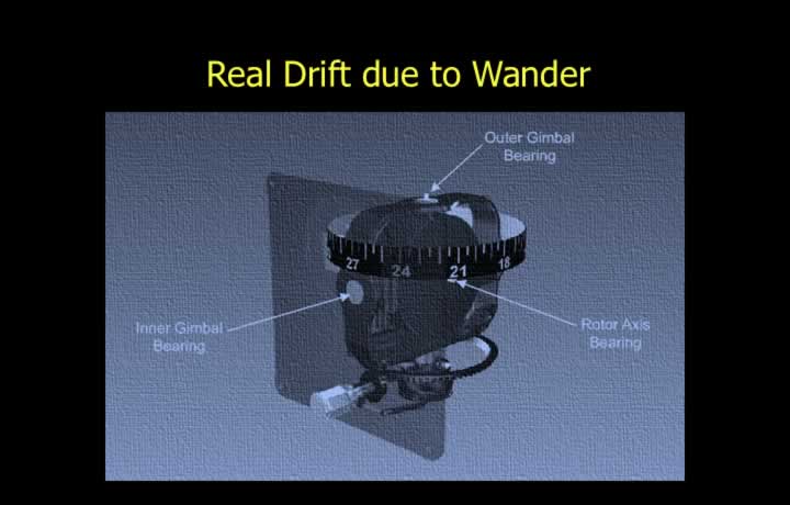
- Real wander is caused by manufacturing imperfections or wear and tear.
- A rotor speed of 10,000 rpm has a drift rate of 1.6° per hour.
- A rotor speed of 20,000 rpm has a drift rate of 1.2° per hour.
- The gyro spin axis actually deviates from its orientation relative to a fixed point in space.
- Real wander is caused because of four types of manufacturing imperfections:
- Imbalance in rotor mass.
- Imperfectly balanced gimbals.
- Uneven rotor bearing friction.
- Uneven gimbal friction.
Apparent Drift due to Earth Rate
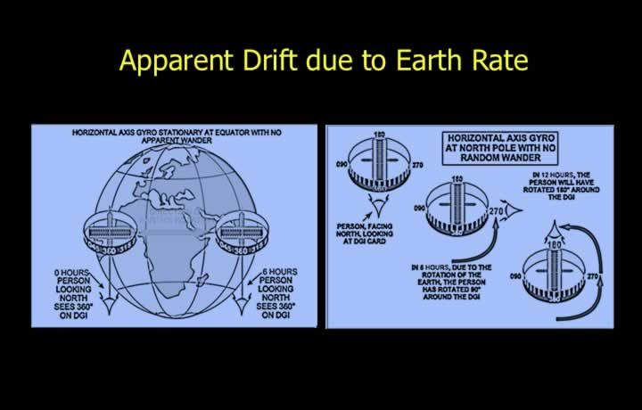
- Apparent drift due to earth rate is caused by the rotation of the Earth.
- A horizontal gyro aligned to true north at a meridian appears to change direction.
- This occurs due to Earth’s rotation and meridian convergence.
- Earth rate varies with latitude because of variation in meridian convergence.
Apparent Drift due to Earth Rate at Equator and Poles
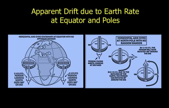
- Earth rate is zero at the equator since meridian convergence is zero.
- The gyro spin axis will not deviate in its horizontal plane.
- Earth rate is maximum at the poles since meridian convergence is maximum.
- The gyro spin axis will deviate by 360° in 24 hours.
- Therefore, the spin axis deviates by 15° per hour.
Apparent Drift due to Earth Rate at Mid-Latitudes
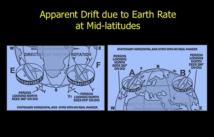
- Earth rate varies with latitude because of variation in meridian convergence.
- Apparent drift due to earth rate = 15 × sin(latitude) (°/hour).
- Gyro north is the north in the original meridian where the gyroscope was aligned.
Earth Rate in Southern and Northern Hemisphere
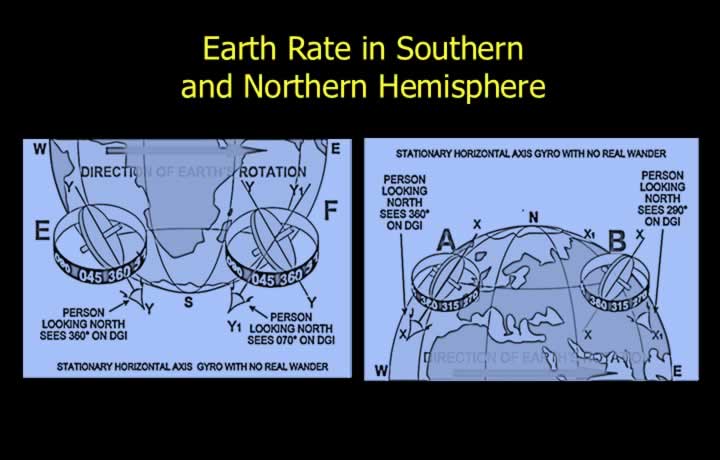
- Southern Hemisphere:
- True north increases with respect to gyro north.
- Example: True north is 070 when gyro north is 360.
- Earth rate is considered positive.
- Northern Hemisphere:
- True north decreases with respect to gyro north.
- Example: True north is 290 when gyro north is 360.
- Earth rate is considered negative.
Latitude Nut Correction
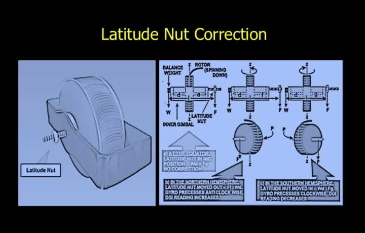
- The latitude nut is used to correct apparent drift due to earth rate.
- It creates real wander by varying rotor speed to correct earth rate.
- The real wander is equal and opposite to the error caused by earth rate.
- The setting is correct only at a particular latitude.
- The latitude nut moves out north of the equator and in south of the equator.
Latitude Nut Movement
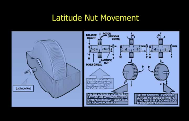
- The DGI is free of earth-rate drift at the corrected latitude.
- Latitude nut correction is inaccurate in the following cases:
- Rotor speeds other than the designed speed.
- Latitudes other than the designed latitude.
Apparent Drift due to Transport Wander
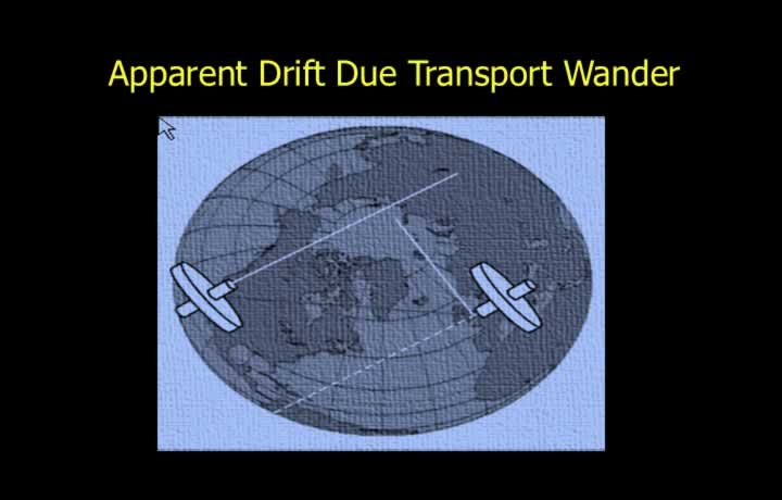
- Apparent drift due to transport wander occurs because of aircraft movement.
- The gyro spin axis appears to shift from gyro north due to transport wander.
- Transport wander occurs during easterly or westerly movement.
- Flight along the equator has zero transport wander.
- Transport Wander Formula:
Easterly component of ground speed (NM/min) × tan(latitude) = Drift (°/hour)
Transport Wander in Northern and Southern Hemisphere
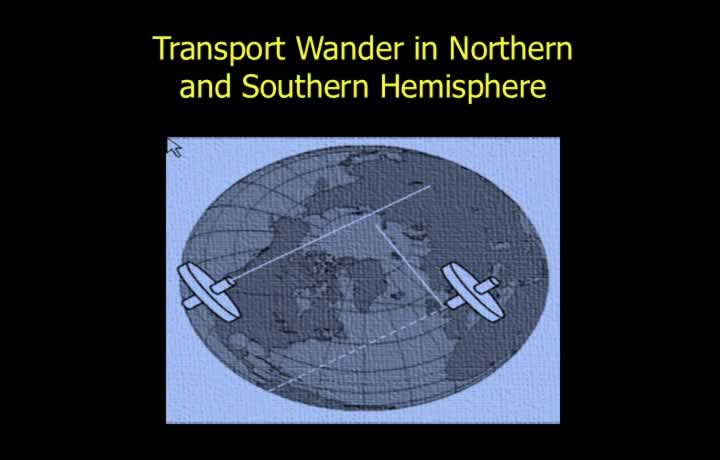
- Northern Hemisphere:
- No effect during northerly or southerly flight.
- Easterly drift is the same as earth-rate drift (negative).
- Westerly drift is opposite to earth-rate drift (positive).
- Southern Hemisphere:
- The above rules are reversed.
Total Apparent Drift
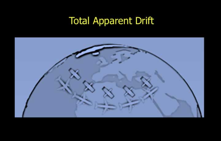
- Total apparent drift is the sum of earth rate and transport wander.
- Earth Rate: 15 × sin(latitude) (°/hour)
- Transport Wander: Easterly component of ground speed (NM/min) × tan(latitude) (°/hour)
- Add both values if they have the same sign.
- Subtract them if they have opposite signs.
Direction of Drift and Topple
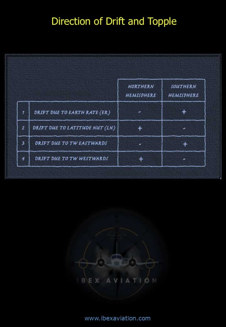
Refer to the drift and topple direction diagram for the Directional Gyro Indicator (DGI).
Total Drift Calculation of a DGI
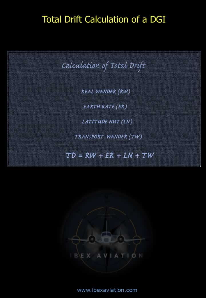
Use the earth rate and transport wander formulas above to calculate the total drift of a Directional Gyro Indicator.