Radio Wave Propagation – Movement of Radio Wave from the Transmitter to Receiver
Radio wave propagation is the process by which radio waves travel from a transmitting antenna to a receiving antenna. It enables wireless communication over short and long distances through the atmosphere or space. The main types of radio wave propagation are ground wave, sky wave, and space wave propagation.
Introduction to Radio Wave Transmission
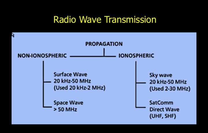
- The ionospheric layer is located in the upper levels of the stratosphere.
- Radio waves can propagate with or without using the ionosphere.
- Non-ionospheric propagation occurs without using the ionosphere.
- Ionospheric propagation takes place using the ionospheric layer.
Types of Propagation
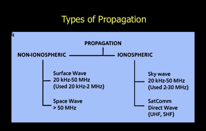
- Non-ionospheric propagation does not pass through the ionosphere.
- Surface waves and space waves are collectively known as ground waves.
- Ground waves propagate without using the ionosphere.
- Ionospheric propagation involves radio waves passing through the ionosphere.
- Direct waves and sky waves are types of ionospheric propagation.
Propagation without using Ionospheric Layers
Surface Waves
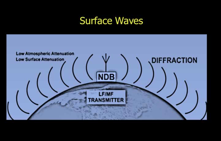
- Low Frequency (LF), Medium Frequency (MF), and High Frequency (HF) waves travel as surface waves.
- Surface wave frequencies range from 20 kHz to 50 MHz.
- In aviation, frequencies between 20 kHz and 2 MHz are commonly used.
- LF, MF, and HF waves experience relatively low atmospheric and surface attenuation.
- High diffraction enables surface waves to bend around the Earth’s surface.
- Surface waves are used for long-range NDB navigation and long-distance communication.
Types of Space Waves
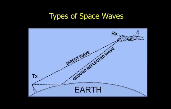
- Direct waves and ground-reflected waves are the two types of space waves.
- Direct waves propagate using the line-of-sight principle.
- Ground-reflected waves reach the receiver after reflection from the Earth’s surface or obstacles.
- Ground reflections may introduce errors in navigational equipment.
Space Waves
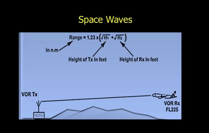
- Very High Frequency (VHF) and Ultra High Frequency (UHF) signals above 50 MHz propagate as space waves.
- Space waves experience very little diffraction.
- The maximum range depends on the line-of-sight distance.
- Approximate radio horizon formula:
Maximum Range = 1.23 × (√Height of Transmitter + √Height of Receiver)
Propagation using Ionospheric Layers
Ionosphere
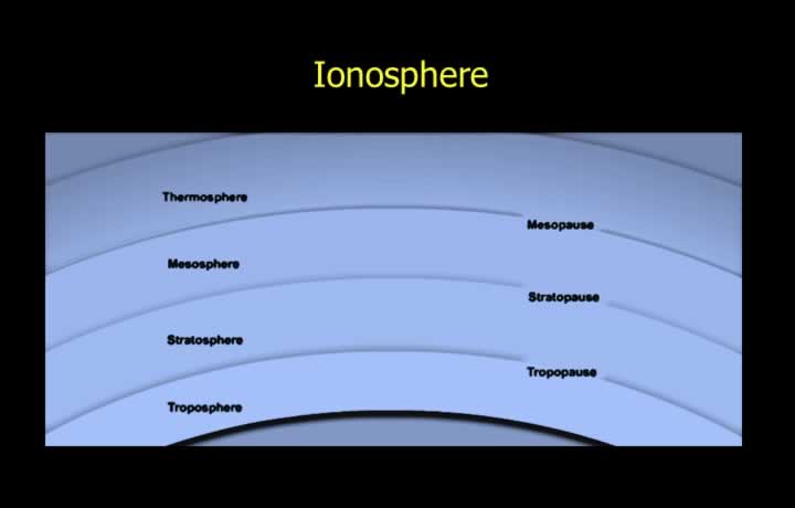
- The ionosphere is located in the upper atmosphere.
- It contains negatively charged free electrons produced by ionized gases.
- Ionisation is the process of removing electrons from atoms.
Ionospheric Attenuation
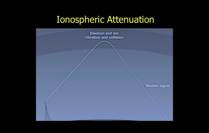
- Radio waves are both refracted and attenuated in the ionosphere.
- Attenuation causes a loss of signal energy.
- Collisions between radio waves and free electrons reduce signal strength.
- Refraction causes some radio waves to return to Earth.
- Ionospheric attenuation is greater at lower frequencies.
- Solar radiation increases ionisation levels.
D Layer of the Ionosphere
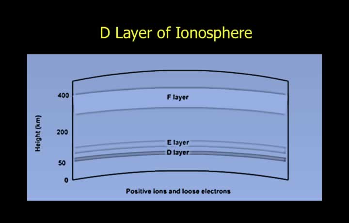
- The ionosphere consists of D, E, and F layers.
- The Kennelly (D) Layer is located approximately 75 km above the Earth’s surface.
- It produces only limited refraction because of low ionisation.
E and F Layers of the Ionosphere
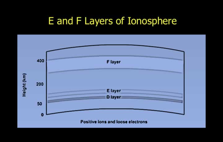
- The Heaviside (E) Layer is located approximately 125 km above Earth.
- It refracts frequencies up to approximately 10 MHz.
- The Appleton (F) Layer is located approximately 225 km above Earth.
- It provides strong refraction due to high ionisation levels.
Variation in D and E Layers
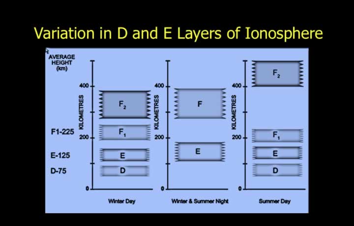
- Maximum ionisation occurs near the center of each ionospheric layer.
- The D layer forms at sunrise and disappears after sunset.
- The E layer lowers at sunrise and rises again after sunset.
Variation in the F Layer
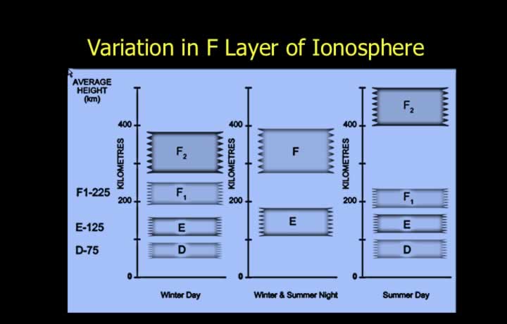
- The F layer splits into F1 and F2 layers during the day.
- The two layers merge again after sunset.
- The altitude of the F2 layer varies with the season.
- During summer it may rise to approximately 400 km.
- During winter it remains near 225 km.
Sky Waves
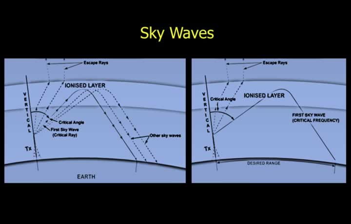
- Radio waves entering the ionosphere are refracted and may return to Earth as sky waves.
- Sky-wave propagation is possible between approximately 2 MHz and 50 MHz.
- LF, MF, and HF bands can propagate as sky waves under suitable conditions.
Terminologies in Ionospheric Propagation
Critical Angle and Critical Frequency
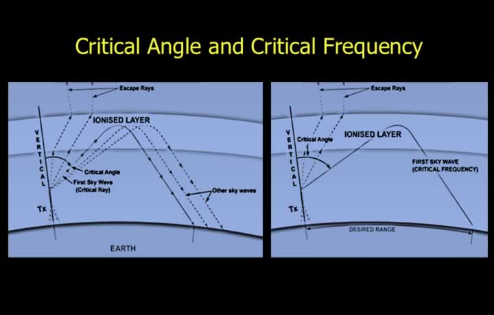
- The critical angle is the minimum transmission angle that allows a sky wave to return to Earth.
- Signals transmitted below the critical angle become escape rays.
- The critical angle depends on ionisation level and transmission frequency.
- Higher ionisation decreases the critical angle.
- Higher transmission frequency increases the critical angle.
- Critical frequency is the highest frequency that will return to Earth when transmitted vertically.
- Higher ionisation increases the critical frequency.
Skip Distance and Dead Space
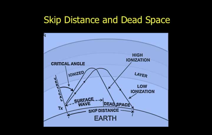
- Skip distance is the distance from the transmitter to the point where the first sky wave returns to Earth.
- Higher ionisation decreases skip distance.
- Higher frequencies increase skip distance.
- Higher reflecting layers also increase skip distance.
- Dead space is the area between the end of the surface-wave range and the beginning of the sky-wave range.
- Dead space decreases as skip distance decreases.
Multi-Hop Propagation
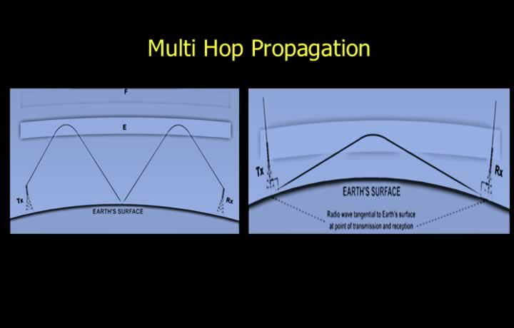
- Multi-hop propagation greatly increases sky-wave communication range.
- It occurs when sky waves are repeatedly reflected between the Earth and the ionosphere.
- It is more common with high-power transmissions.
- Maximum range is achieved when radio waves travel nearly tangential to the Earth’s surface.
- Ground-based HF transmitters are designed to radiate at low elevation angles.
Sky Waves at Night
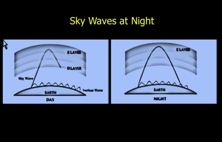
- Sky-wave propagation in LF and MF bands differs significantly between day and night.
- During daylight, the D layer absorbs most sky waves.
- At night, the D layer disappears, allowing greater sky-wave propagation.
- Night-time sky waves may interfere with surface waves.
- LF and MF Non-Directional Beacons (NDBs) may produce erroneous indications at night.
Maximum Usable Frequency (MUF)
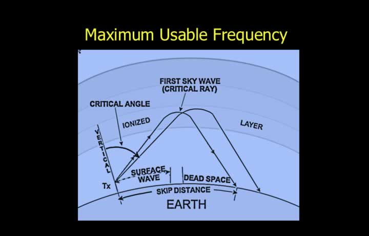
- MUF is the highest frequency that can be used for ionospheric communication.
- Frequencies above the MUF pass through the ionosphere as escape rays.
- MUF provides the shortest ionospheric path.
- It experiences minimum attenuation and static interference.
- MUF is highest around midday when ionisation is strongest.
Optimum Working Frequency (OWF)
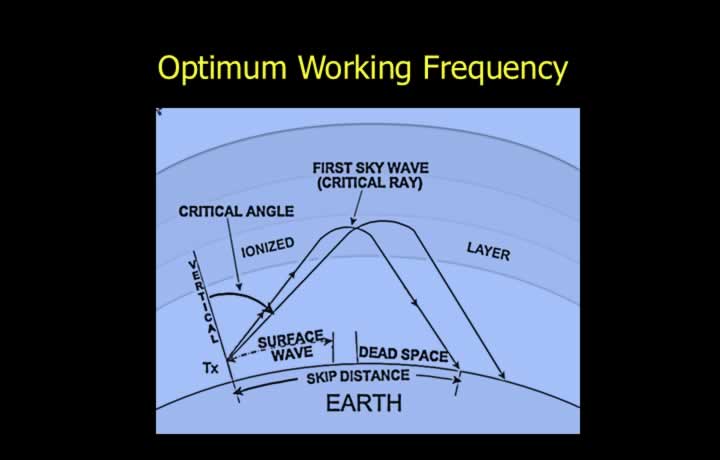
- Optimum Working Frequency (OWF) is approximately 85% of the MUF.
- Using the OWF provides a safety margin against changes in ionospheric conditions.
- HF communication frequencies are generally reduced at night because ionisation decreases.
Increase and Decrease of Signal Strength
Fading
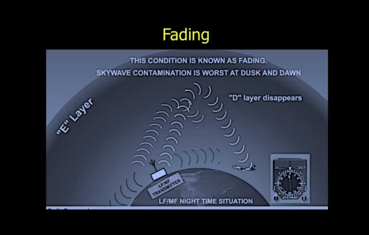
- Fading is the variation in received signal strength.
- It is caused by weak signal strength.
- Long distance, low transmitter power, weather, and terrain contribute to fading.
Multipath Fading
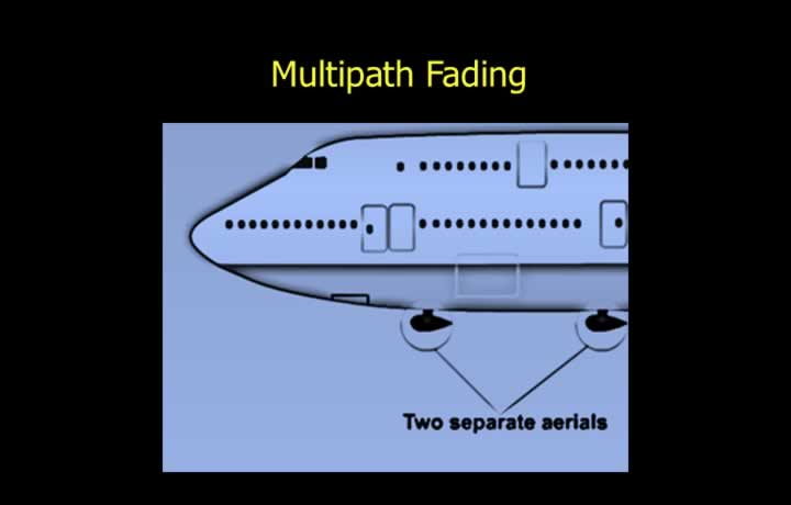
- Multipath fading occurs when both surface waves and sky waves of the same signal reach the receiver.
- Out-of-phase reception causes interference.
- Multipath fading can be reduced by:
- Using different frequencies for transmission and reception.
- Using space diversity with two or more receiving antennas.