
Landing using Instrument Landing System (ILS)
ILS (Instrument Landing System) is a precision radio navigation system that guides aircraft during landing. It provides horizontal (localiser) and vertical (glide slope) guidance to align the aircraft with the runway. ILS enables safe and accurate landings, especially in poor visibility and bad weather.
Introduction to ILS
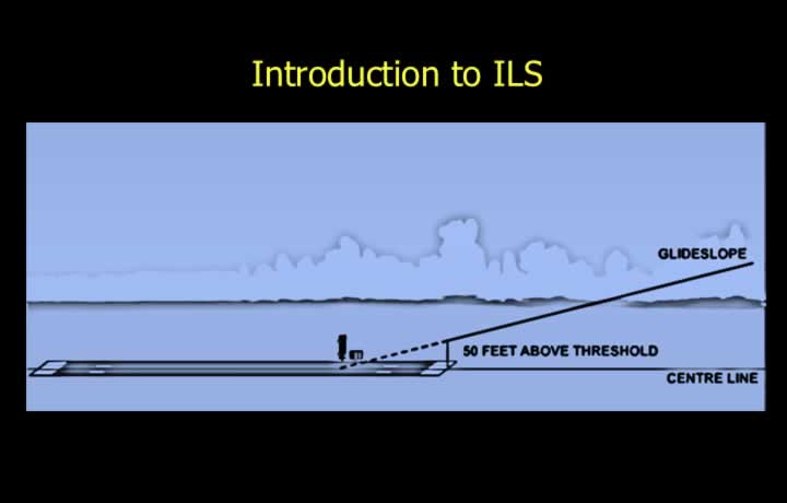
- ILS provides horizontal and vertical guidance using the Localiser and Glide Path.
- The ILS reference datum is located on the runway centreline at 50 ft above the threshold.
- Localiser frequencies range from 108.00 to 111.975 MHz in the VHF band.
- Glide Slope frequencies range from 329.15 to 335.00 MHz in the UHF band.
- Each Localiser is frequency-paired with its corresponding Glide Slope, so selecting the Localiser automatically selects the Glide Slope.
- Marker Beacons are low-power radio transmitters that provide distance alerts.
- A DME paired with the ILS provides distance information during final approach.
Localiser of ILS
Principle of ILS Localiser
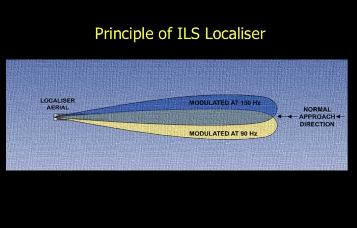
- The Localiser transmits two overlapping lobes along the runway approach path.
- Both lobes use the same carrier frequency but different audio modulation.
- The right-hand (blue) sector is modulated at 150 Hz.
- The left-hand (yellow) sector is modulated at 90 Hz.
- Equal 90 Hz and 150 Hz modulation indicates alignment with the runway centreline.
- The Difference in Depth of Modulation (DDM) is zero on the centreline.
- DDM increases as the aircraft deviates from the extended runway centreline.
Coverage of ILS Localiser (Normal Approach)
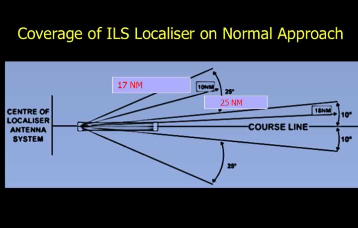
- Coverage depends on the glide path angle.
- Normal approach coverage is 10° up to 25 NM.
- Coverage increases to 35° up to 17 NM.
- Outside these limits, false beams make Localiser indications unreliable.
Coverage of ILS Localiser (Steep Approach)
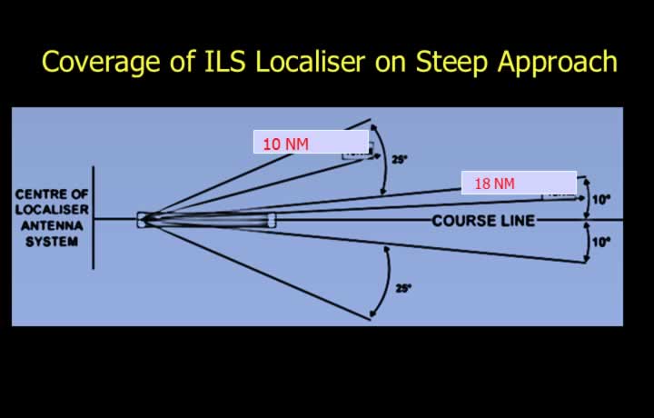
- Coverage depends on the glide path angle.
- Steep approach coverage is 10° up to 18 NM.
- Coverage increases to 35° up to 10 NM.
- False beams make Localiser indications unreliable outside these limits.
Back Beam of ILS Localiser
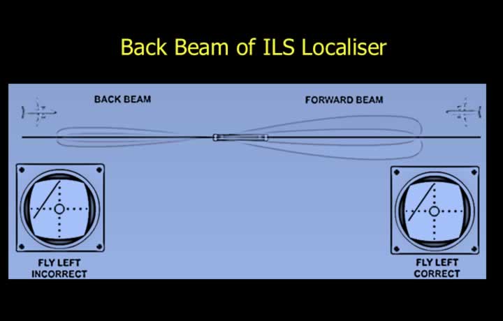
- The Localiser antenna also radiates a back beam in the opposite direction.
- Back beam indications are reversed when approaching from the opposite runway.
- The indications effectively become a “what not to do” display.
- During a missed approach, back beam indications may provide useful guidance.
- Back beam approaches are approved only in certain countries.
ILS Localiser Indications
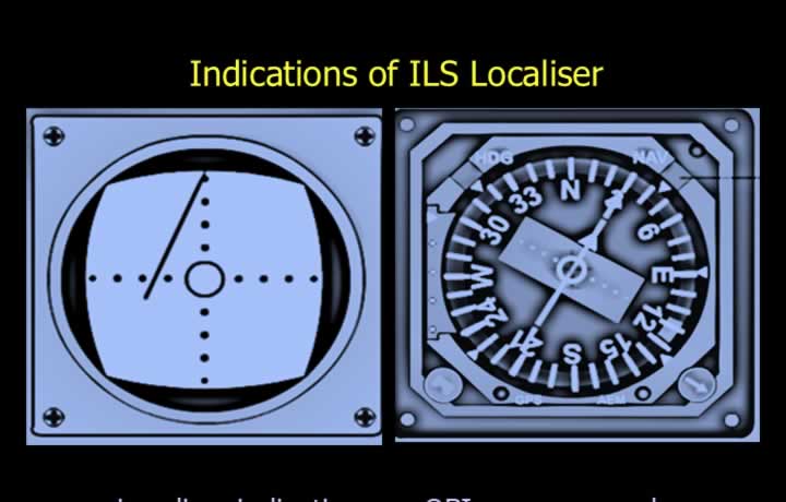
- Localiser indications on the CDI/OBI provide command guidance toward the runway centreline.
- Needle Left → Fly Left.
- Needle Right → Fly Right.
- On a five-dot indicator, full-scale deflection equals 2.5°.
- Each dot represents 0.5°.
- The aircraft is considered established when within half-scale deflection.
- HSI displays Localiser guidance using an arrow or deviation needle.
- A warning flag appears when the carrier signal or one modulation signal is lost.
Glide Path of ILS
Principle of ILS Glide Path
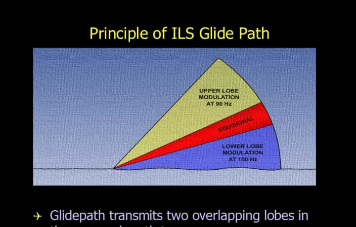
- The Glide Path transmits two overlapping lobes along the approach path.
- Both lobes share the same carrier frequency with different audio modulation.
- The lower (blue) sector is modulated at 150 Hz.
- The upper (yellow) sector is modulated at 90 Hz.
- Equal modulation indicates the correct glide path.
- DDM is zero on the correct glide path.
- DDM increases as the aircraft moves above or below the glide path.
- The receiver displays Fly Up or Fly Down guidance.
False Glide Path
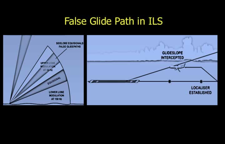
- A false glide path normally occurs at approximately twice the correct glide angle.
- It is caused by antenna characteristics and reflected radio waves.
- The Glide Slope should always be intercepted from below.
- The aircraft should first be established on the Localiser before intercepting the Glide Path.
Horizontal Coverage of Glide Path
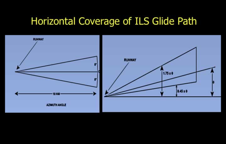
- Coverage depends on the glide angle.
- For a normal approach, horizontal coverage extends approximately 8° up to 10 NM.
- For a steep approach, coverage is reduced to approximately 8 NM.
Vertical Coverage of Glide Path
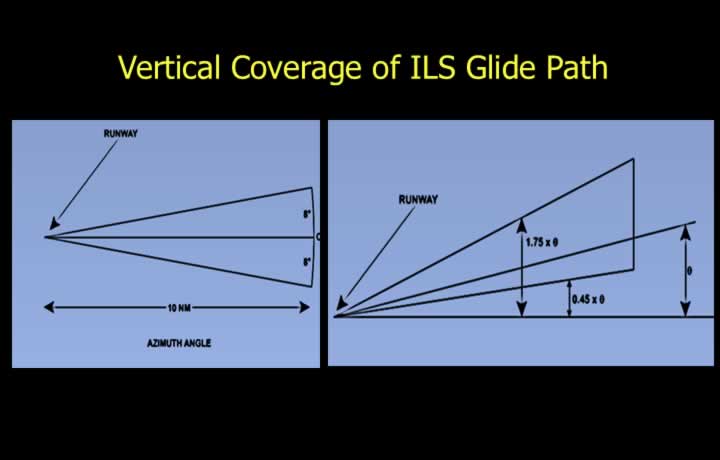
- Vertical coverage is measured relative to the published glide angle.
- Lower limit is 0.45 × glide angle below the nominal glide path.
- Upper limit is 1.75 × glide angle above the nominal glide path.
- For a standard 3° glide slope:
- Coverage extends from 1.65° to 2.25° relative to the glide path.
- Equivalent elevation range is approximately 1.35° to 5.25° above the horizon.
Course Deviation Indicator (ILS Mode)
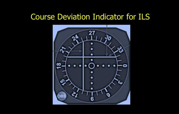
- Glide Path indications provide command guidance.
- Needle Up → Fly Up.
- Needle Down → Fly Down.
- Full-scale Glide Slope deflection equals approximately 0.7°.
- Each dot on a five-dot indicator represents approximately 0.14°.
- Maximum safe deviation is half-scale (0.35° above or below).
Measurement of Distance to Touchdown
ILS Marker Beacons
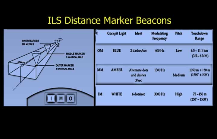
- Marker Beacons transmit on 75 MHz using an elliptical or fan-shaped radiation pattern.
- Outer Marker (OM)
- Located 3.5–6 NM from touchdown.
- Blue light.
- 400 Hz tone with two dashes per second.
- Middle Marker (MM)
- Located approximately 3,500 ft from touchdown.
- Amber light.
- 1300 Hz alternating dots and dashes.
- Inner Marker (IM)
- Located 250–1,500 ft from touchdown.
- White light.
- 3000 Hz tone with six dots per second.
Errors and categories of ILS
ILS Categories
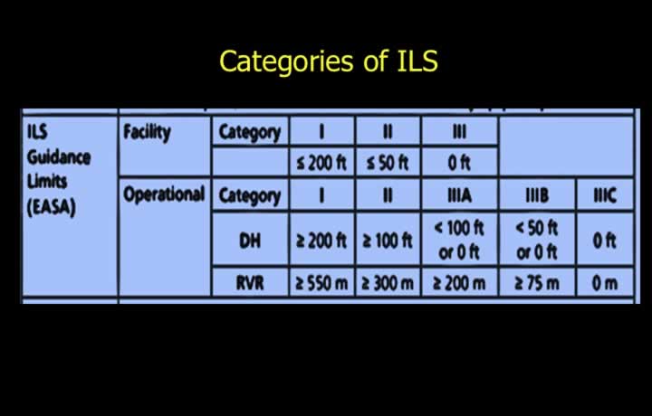
- ILS Categories describe only the ground installation.
- Operational use also depends on:
- Airport procedures.
- Airborne equipment capability.
- Flight crew qualifications.
ILS Ground Monitoring
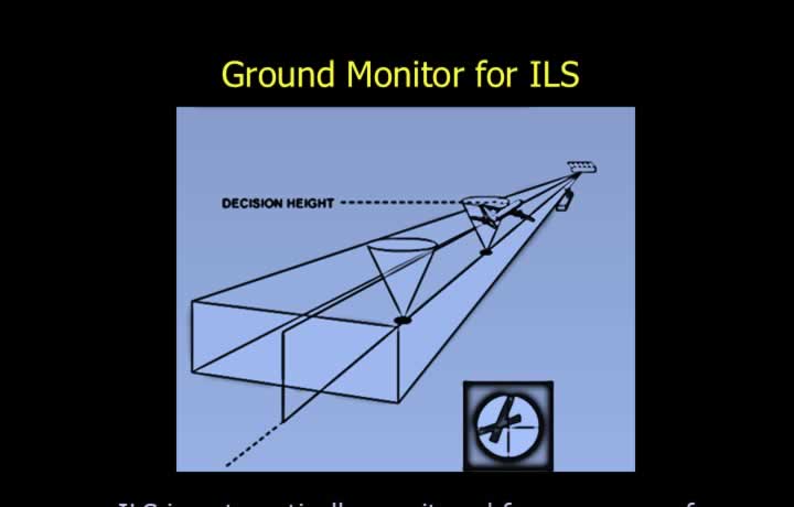
- The ILS is continuously monitored within its protected coverage area.
- If limits are exceeded, transmissions cease and station identification is removed.
- Category II or III systems may automatically downgrade to a lower category.
- Monitoring activates when:
- Localiser shifts beyond allowable limits.
- Centreline error exceeds 35 ft (CAT I), 25 ft (CAT II), or 20 ft (CAT III).
- Glide Path angle changes by more than 0.075 × the published glide angle.
- Transmitter power decreases by more than 50%.
Errors of ILS
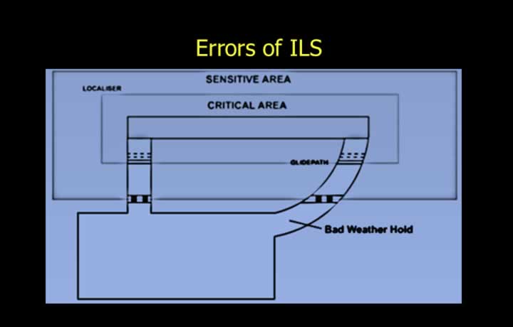
- ILS indications should always be cross-checked due to inherent system limitations.
- Beam bending caused by atmospheric conditions.
- Scalloping caused by reflected radio waves.
- Beam noise from transmitter or external interference.
- Restricting vehicles within critical and sensitive areas minimises interference.
- Aircraft should remain clear of sensitive areas during poor weather.
- Station identification must always be positively received before using the ILS.
Limitations of ILS
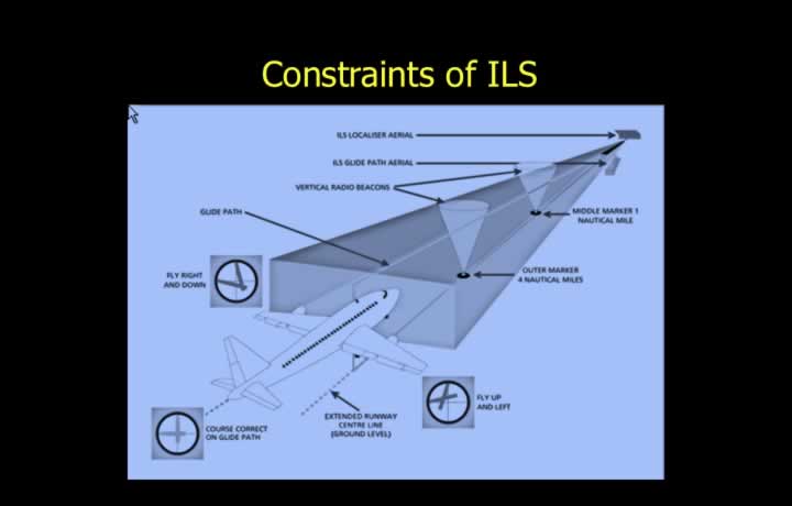
- ILS is limited to approximately 40 frequency channels.
- Requires a large, flat, obstacle-free installation area.
- Fixed Glide Path is unsuitable for some STOL aircraft.
- Only a limited number of aircraft can be accommodated simultaneously.
- Terrain may prevent installation in mountainous regions.
- The ILS critical area must be protected from interference.
- Nearby civilian FM broadcasts may cause interference.