
Flight Management System (FMS)
The Flight Management System (FMS) is an onboard computer that manages flight planning, navigation, and aircraft performance. It calculates the optimum route, speed, altitude, and fuel usage, and guides the aircraft along the planned flight path. The FMS reduces pilot workload, improves fuel efficiency, and enhances the accuracy and safety of flight operations.
Introduction to Flight Management System
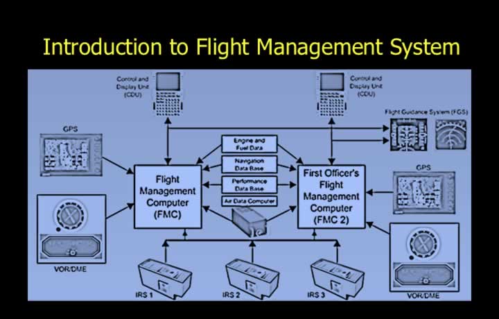
- The Flight Management System (FMS) provides continuous automatic navigation, guidance and performance management.
- A typical FMS consists of:
- Two Flight Management Computers (FMCs).
- Three Inertial Reference Systems (IRS).
- Global Positioning System (GPS).
Modes of Operation of FMS
- Lateral Navigation (LNAV) provides automatic track, heading and radial guidance.
- Vertical Navigation (VNAV) provides optimum climb, cruise and descent profiles.
Lateral Navigation (LNAV)
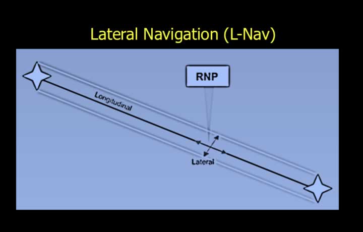
- LNAV provides lateral guidance to assist pilots during all phases of flight.
- Functions include:
- Take-off and Standard Instrument Departure (SID).
- En-route waypoint navigation.
- Standard Terminal Arrival Routes (STAR).
- Instrument approach procedures.
- Missed approach procedures.
- Navigation to an alternate airport.
Vertical Navigation (VNAV)
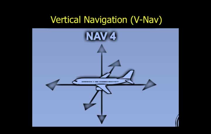
- VNAV provides vertical guidance throughout the flight.
- Functions include:
- Noise abatement procedures.
- ATC speed restrictions.
- Optimum rate of climb.
- Economic climb speed.
- Optimum cruise settings and cruise speed.
- Step climb planning.
- Top of Descent (TOD) calculation.
- Descent profile management.
Components of Flight Management System
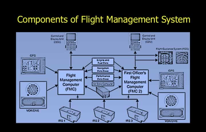
- The FMS integrates inputs from:
- Flight Management Computer (FMC).
- Control Display Unit (CDU).
- Two or Three Inertial Reference Systems (IRS).
- Air Data Computer (ADC).
- Radio navigation aids (VOR/DME).
- Navigation and Performance Databases.
- Engine and fuel management systems.
- Flight Guidance System.
- Flight Director and/or Autopilot.
Operation of Flight Management Systems
FMS Control Display Unit (CDU)
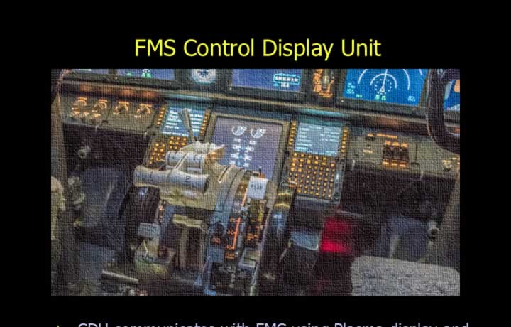
- The CDU communicates with the FMC through a display and keypad.
- Allows both draft and final data entry.
- Provides advisory and alert messages to the flight crew.
FMS Pages
Pre-flight Pages
- IRS Initialisation.
- Dispatch Information.
- Flight Plan Route.
- Zero Fuel Weight.
- Cruise Altitude.
In-flight Pages
- Display Information.
- Advisory Messages.
- Alert Messages.
Performance Pages
- Climb Performance.
- Cruise Performance.
- Thrust Settings.
- Maximum and Minimum Altitudes.
- Expected Fuel Flow.
CDU Warning Lights
- Display Light – Indicates incorrect page selection.
- FAIL Light – Indicates system failure.
- MESSAGE Light – Indicates messages in the scratchpad.
- OFFSET Light – Indicates offset flight operation.
Types of Databases in an FMS
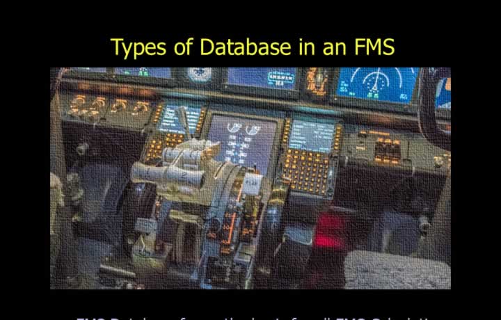
- The FMS database forms the basis for all navigation and performance calculations.
Main Navigation Database
- Valid for 28 days (AIRAC cycle).
- The current and next AIRAC databases are loaded before operation.
- Contains:
- Airways.
- Navigation aids.
- Instrument approaches.
- Standard Instrument Departures (SID).
- Standard Arrival Routes (STAR).
- This database cannot be modified by pilots.
Supplemental Navigation Database
- A permanent database loaded by the aircraft operator.
Temporary Navigation Database
- Loaded by the operator for a single flight only.
Performance Database
- Contains aircraft-specific performance information including:
- Climb performance.
- Cruise performance.
- Thrust settings.
- Aircraft weights.
- Fuel flow.
- Altitude limitations.
- Updated by maintenance personnel.
Modes of Flight Management Systems<>
FMS Operating Modes
Dual Mode
- Normal operating mode.
- Each FMC performs independent calculations.
- The results are cross-checked and synchronized.
- Identical information is displayed to both pilots.
Independent Mode
- Each FMC operates independently.
- Displays may differ between the Captain and First Officer.
- Automatic or manual changeover is available.
Single Mode
- Used after failure of one Flight Management Computer.
- The remaining FMC supplies data to both pilot displays.
Backup Mode
- Used if both Flight Management Computers fail.
- The Inertial Reference System supplies navigation information directly.
- The Electronic Flight Information System (EFIS) displays IRS data.
- The Autopilot is disconnected from the FMS.
FMS Start-up Sequence
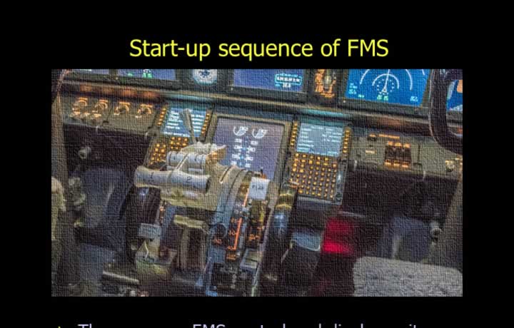
- Pages are selected using the CDU keypad.
- Navigation keys allow movement between pages.
Start-up Pages
- IDENT Page
- Aircraft model.
- Engine rating.
- AIRAC cycle verification.
- Position Initialisation Page
- Parking stand position.
- Route Page
- Departure airport.
- Destination airport.
- Route.
- Waypoints.
- Performance Page
- Gross weight.
- Cruise altitude.
- Fuel required.
- Forecast winds.
- ISA deviation.
- Temperature.
- Cost Index.
- N1 Limit Page
- Engine thrust limitation to reduce engine wear during climb.
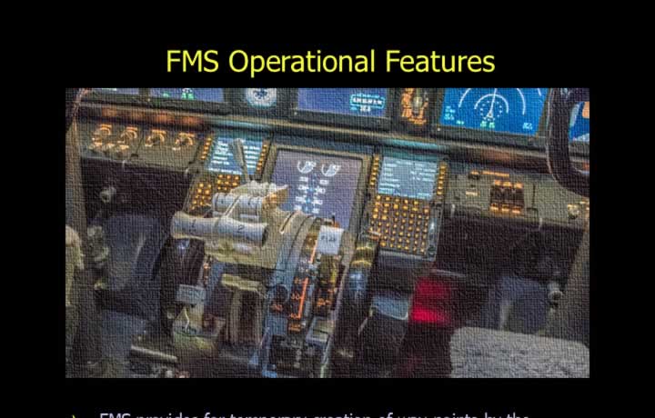
FMS Operational Features
Waypoint Creation
- Temporary waypoints may be created using:
- Latitude and Longitude.
- Bearing and Distance.
- Distance Along Track.
Automatic Position Updates
- The FMS updates aircraft position automatically using:
- Take-off/Go-around switch.
- Manual displaced runway threshold input.
Automatic Calculations
- Cost Index calculates optimum flight speed based on:
- Fuel cost.
- Maintenance cost.
- Engine life.
- Trip time.
- Required Time of Arrival (RTA) calculations determine:
- Take-off time.
- Cruise speed.
- Cost Index adjustments.
- Arrival time at destination.
Alert Messages
- Thrust required.
- Incompatible SID or STAR.
- ILS frequency error.
- Insufficient fuel.
Advisory Messages
- Maximum flight level limitations.
- Performance-related advisories.
Errors and Accuracy Levels of FMS<>
Schuler and Ramp Errors

- FMS accuracy is affected by errors originating in the Inertial Navigation System (INS).
- Schuler Error (bounded error) results from manufacturing and alignment limitations.
- Ramp Error (unbounded error) increases with flight time.
- The FMS minimises these errors using Kalman Filtering.
Kalman Filtering
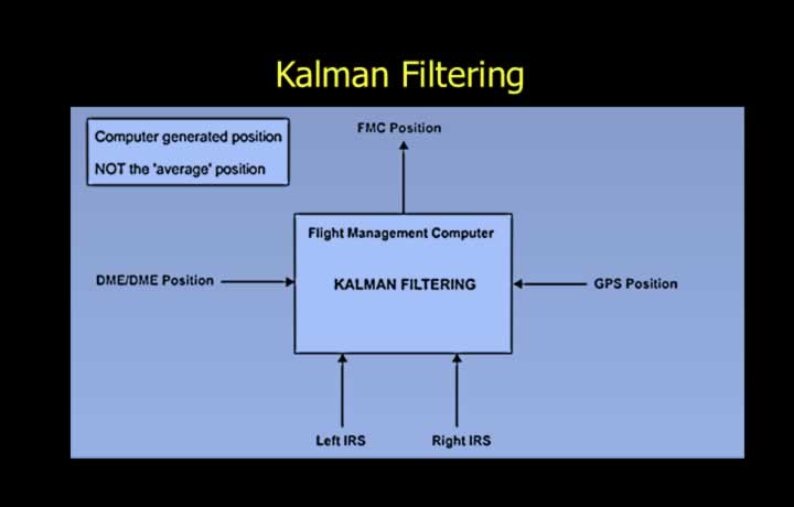
- Kalman Filtering is a statistical technique used to determine the most probable aircraft position.
- The calculated position is not a simple average of all inputs.
- A mathematical algorithm assigns different weights based on the accuracy of each navigation source.
- The resulting navigation solution is known as the FMC Position.
High Latitude Navigation
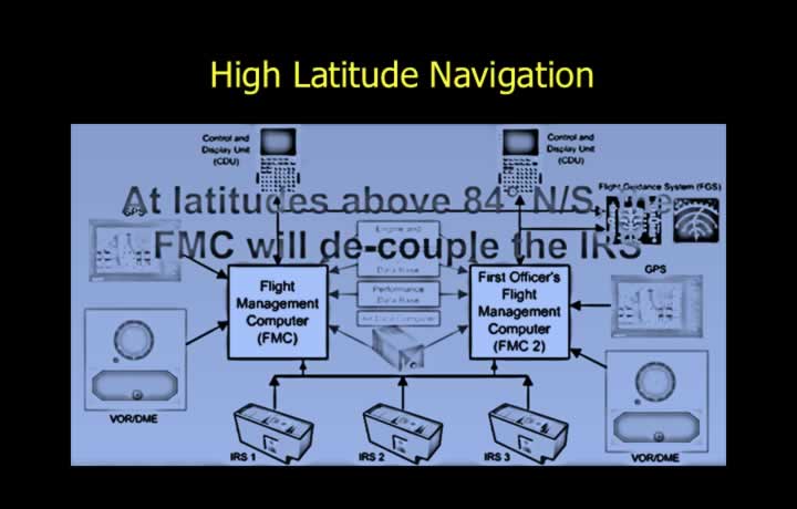
- Above approximately 84° North or South, meridians converge rapidly.
- To prevent navigation errors caused by meridian convergence, each FMC automatically decouples from the opposite IRS.
- Each Flight Management Computer uses only the IRS located on its own side of the aircraft.