
Weather Avoidance and Mapping using Airborne Weather Radar
Airborne weather radar is a radar system installed in an aircraft to detect weather conditions such as rain, thunderstorms, and turbulence ahead. It helps pilots avoid hazardous weather by displaying the location and intensity of storms. This improves flight safety, route planning, and passenger comfort.
Airborne Weather Radar (AWR)
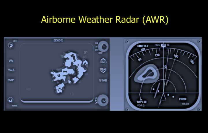
- Airborne Weather Radars are installed onboard aircraft.
- They provide information on weather, clouds, and terrain mapping.
- AWR can be used for fixing aircraft position using range and bearing from ground features.
- AWR consists of:
- Transmitter
- Receiver
- Antenna
- Display with control panel
- Heating elements in the radar housing reduce the risk of icing.
Principle of Airborne Weather Radar
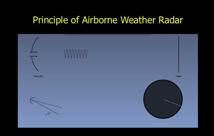
- AWR operates on the principle of Primary Radar.
- Bearing by Search Light Principle: Direction of returned signal provides bearing information.
- Slant Range by Echo Principle: Time delay between transmitted and received pulses provides range information.
Antenna of Airborne Radar
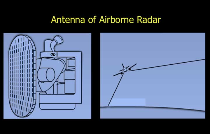
- Airborne radars use Flat Plate Slotted Array Antenna.
- The antenna is mounted on a gyro-stabilised platform.
- The stabilised platform maintains antenna alignment during aircraft pitch and roll movements.
Advantages of Flat Plate Antenna
- Produces narrow beams.
- Requires less power.
- Side lobes are eliminated.
AWR Frequency and Wavelength
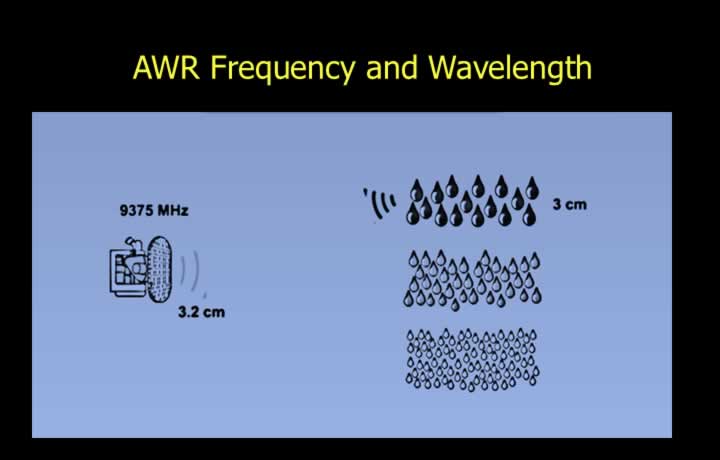
- Large water droplets in thunderstorms are approximately 3 cm in size.
- AWR wavelength is selected to provide effective detection of dangerous clouds.
- The selected wavelength is 3.2 cm.
- A wavelength of 3.2 cm corresponds to a frequency of approximately 9375 MHz.
Beam Width and Resolution
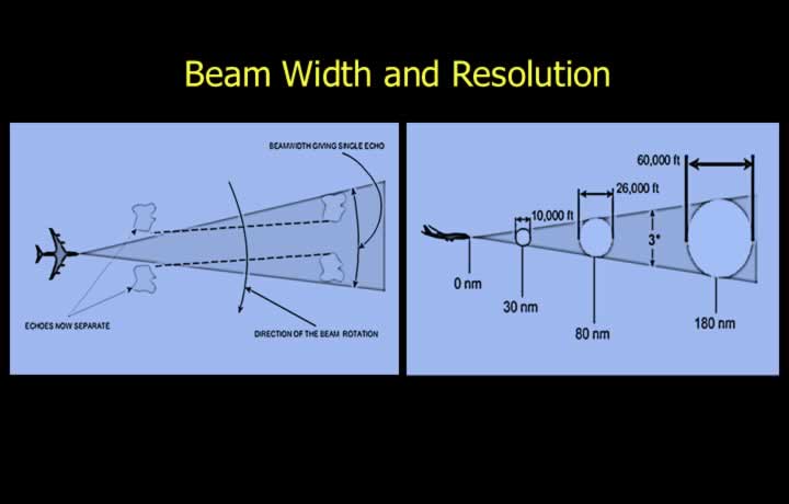
- Resolution of two separate objects depends on beam width.
- A weather radar with a 3° beam width can distinguish clouds separated by:
- 10,000 feet at 30 NM distance.
- 26,000 feet at 80 NM distance.
- 60,000 feet at 180 NM distance.
Airborne Radars for Weather Avoidance
Weather Mode – Conical or Pencil Beam
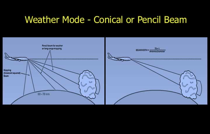
- AWR operates using two different types of beams.
- Conical Beam / Pencil Shaped Beam
- Conical beam is used for weather detection and long-range terrain mapping.
- Pencil beams have a narrow beam width.
- Pencil Beam Width (Degrees) = (70 × Wavelength) / Antenna Diameter
- Narrow pencil beams can distinguish between closely spaced clouds.
Control Panel of Weather Radar
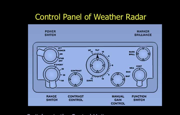
- Stab ON: Keeps antenna horizontal to the earth surface.
- Stab OFF: Locks antenna in the fore and aft axis.
- Range Dial: Selects maximum scan distance.
- Standby Button: Keeps radar in standby or non-operational mode.
- Tilt Dial: Tilts antenna up to 15° up or down.
- Radar can be moved 90° either side of the aircraft nose.
- Function Dial: Selects Map or Weather mode.
- Gain Dial: Manually selects signal strength.
- Manual gain adjustment is available only in Map mode.
Radar Display of Steep Gradient
- Weather mode is the default radar mode.
- It is used for weather detection.
- Manual gain adjustment is not available.
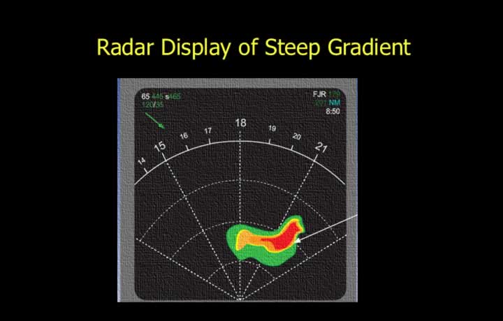
- It detects turbulent clouds based on water droplet size.
- Steep colour gradients indicate highly turbulent clouds.
Colour Coding in Weather Mode
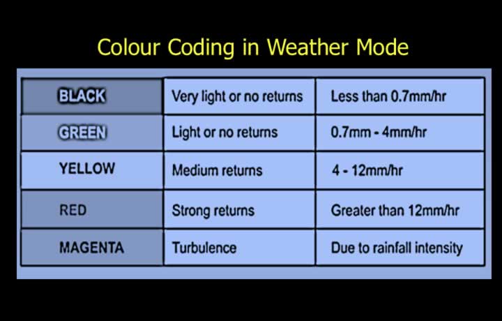
- Severity of turbulence is indicated by colour coding of radar returns.
Display of Dangerous Clouds
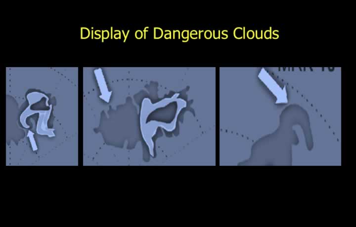
- Severe turbulence may be expected from cloud returns with the following shapes:
- U-shaped returns
- Finger-shaped returns
- Scalloped edges
- Hook-shaped returns
Automatic Gain Control (AGC)
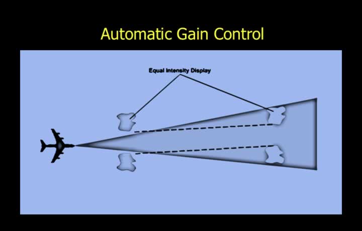
- Weather Radar uses Automatic Gain Control in Weather Mode.
- Similar clouds produce the same intensity returns irrespective of distance.
- A similar cloud at 5 NM and 25 NM will produce similar returns.
- AGC operates up to a range of 25 NM.
Cloud Height Calculation
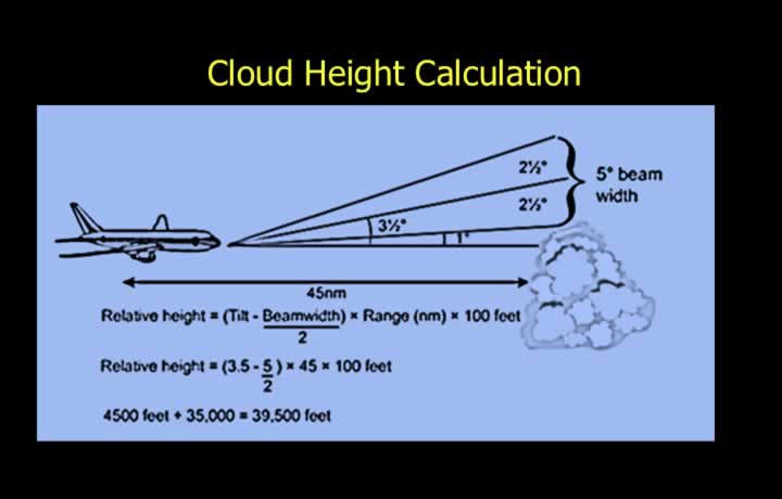
- Radar stabilisation must be switched off.
- The antenna tilt angle is increased or decreased until the cloud disappears.
- Cloud height is calculated using:
Relative Height = (Tilt – Beam Width / 2) × Range in NM × 100 Feet
Controls in Weather Mode
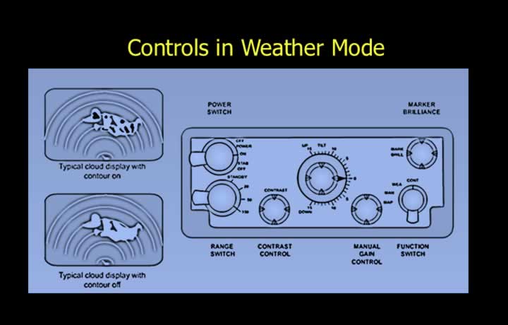
- Manual mode and gain can be selected for ranges beyond 70 NM.
- Contour setting converts colour radar display into black and white.
- Target Alert warns the crew of dangerous clouds beyond selected range.
- Target Alert indication is a flashing red square.
- Conditions for Target Alert:
- Dangerous cloud between 60 and 160 NM.
- Cloud within 15° either side of aircraft heading.
- Range selection less than 50 NM.
- Target Alert button switched ON.
Airborne Radars for Ground Mapping
Map Mode – Cosecant Squared or Fan Beam
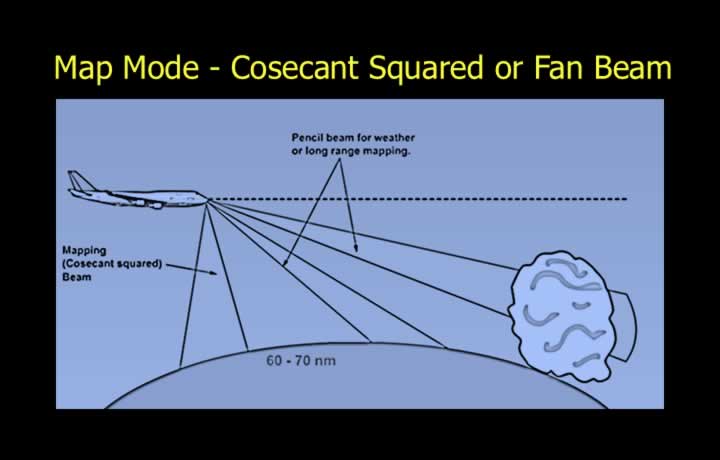
- Uses a cosecant squared or fan-shaped beam.
- Used for short-range ground mapping below 60 NM.
- Transmission power varies according to the cosecant squared value of the depression angle.
- Depression angle can be up to 85° and 3.5° in azimuth.
- Farther parts of the beam receive higher power than nearer parts.
- Provides equal intensity returns from different distances.
- Gain is adjusted manually using the gain dial.
Airborne Radar Returns from Terrain
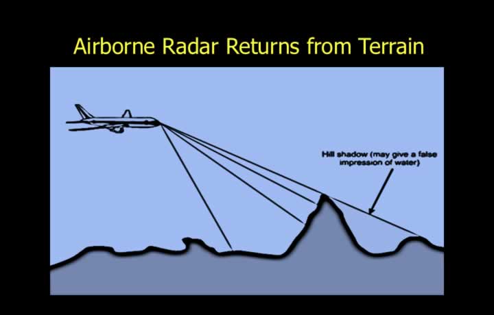
- Radar returns vary depending on terrain type.
- Flat terrain, water, sand, and snow produce weak returns.
- Built-up areas and mountains produce bright returns.
- Mountains create radar shadows.
- Hills hidden behind larger mountains may appear as a series of lakes.
Aircraft Position Using Airborne Radar
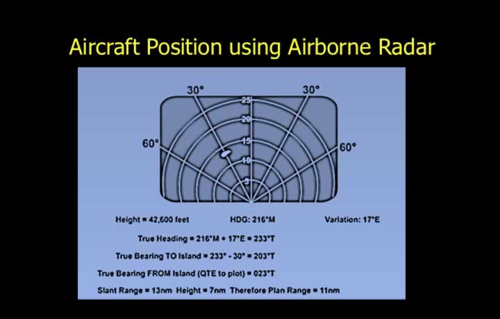
- Aircraft position can be fixed using airborne weather radar.
- Fan or cosecant squared beam is used between 15 and 70 NM.
- Select a prominent ground feature such as a bridge over a river.
- Determine relative bearing and distance using radar.
- Convert relative bearing to true bearing.
- Convert slant range to plan range.
- Plot reciprocal or true bearing with plan range.
Electronic Flight Display System (EFIS)
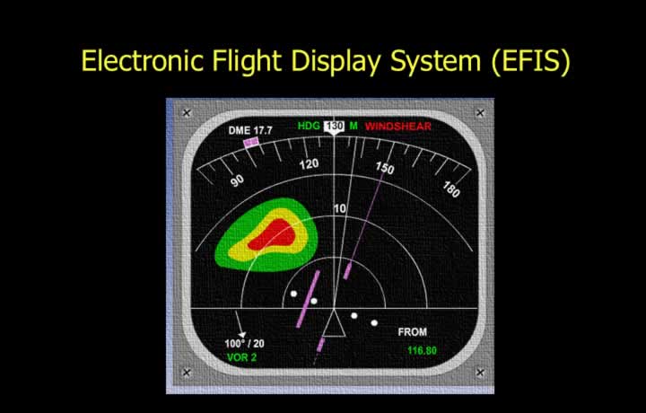
- Modern colour radar features are integrated into Electronic Flight Display Systems.
- Available features include:
- Weather Only Mode
- Weather and Turbulence Mode
- Variable Gain Control for Mapping
- Test Button
- Hold or Pause Button
- Target Alert Facility
- Wind Shear Alert