Radio Detection and Ranging – Radar
Radar based avionics use radio waves to detect and track aircraft. It helps air traffic controllers monitor aircraft positions and maintain safe separation. Radar also supports navigation, weather monitoring, and safe take-off and landing operations.
Pulse Radar
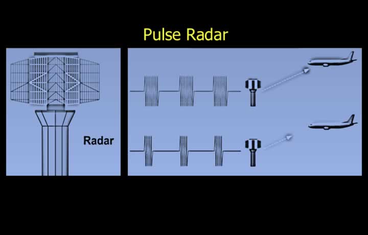
- Radar stands for Radio Detection and Ranging.
- Radar can be used as Ground Radar or Airborne Radar.
- Primary Radar transmits and receives its own reflected pulses.
- The range of a target is calculated from the time taken for the pulse to travel to the target and return to the radar.
- The speed of light is used to calculate the distance to the target.
Continuous Wave Radar
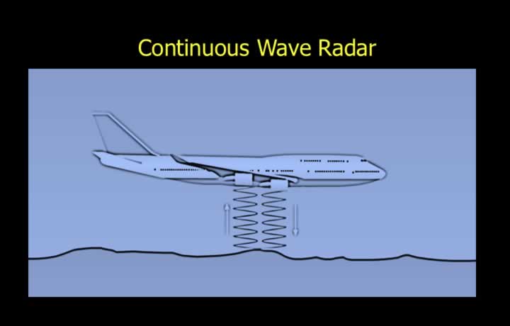
- Continuous Wave Radar is another type of primary radar.
- It transmits and receives reflected continuous waves.
- The range of the target is calculated by measuring the phase difference between transmitted and received signals.
Principle of Primary Radar
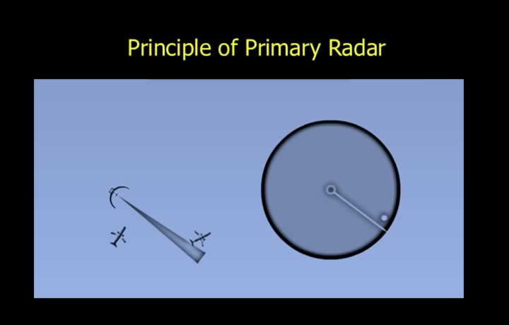
- Primary radar operates on two basic principles:
- Range is determined using the echo principle.
- Bearing is determined using the searchlight principle.
- Primary radar transmits a continuous sequence of pulses towards the target.
- A small portion of the transmitted energy is reflected back and received after a time delay.
- The time delay provides the range of the target.
- The direction of the reflected signal determines the bearing of the target.
Secondary Radar
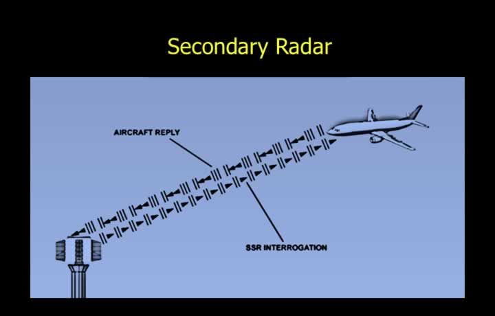
- Secondary Radar transmits an interrogation signal towards the target.
- The target receives the signal and responds by transmitting on a different frequency.
- Secondary Radar requires cooperation from the target equipment.
Parabolic Dish Antenna
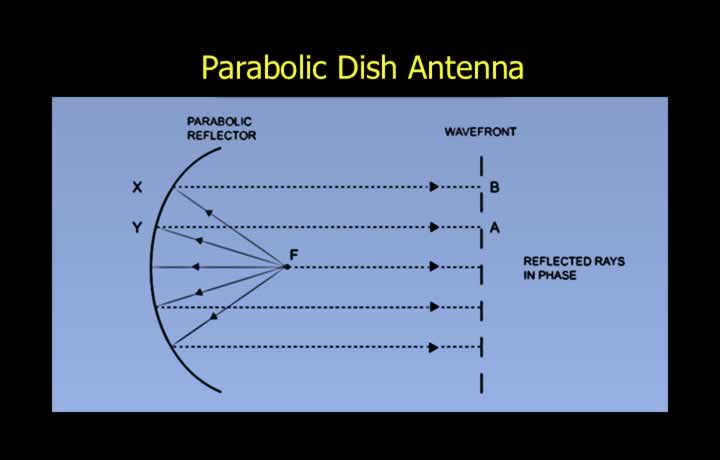
- A Parabolic Dish Antenna consists of a parabolic reflector behind the antenna element.
- Every point on the dish is equidistant from the focal point.
- The focal point is the point where transmitted energy is concentrated.
- The antenna produces narrow, parallel beams in a specific direction.
- Larger dishes produce narrower beams.
- The same antenna is used for both transmission and reception.
- The transmitter must therefore be switched off during reception.
Side Lobes in Parabolic Dish Antenna
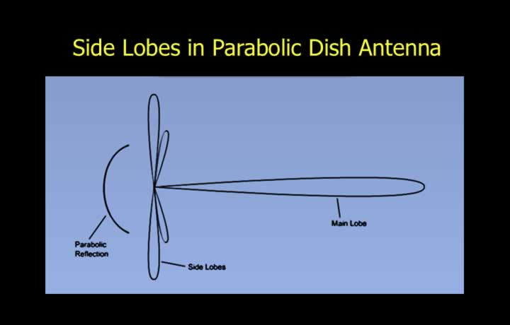
- Parabolic antennas produce additional weaker side lobes.
- Side lobes may detect targets outside the required coverage area.
Flat Plate Antenna
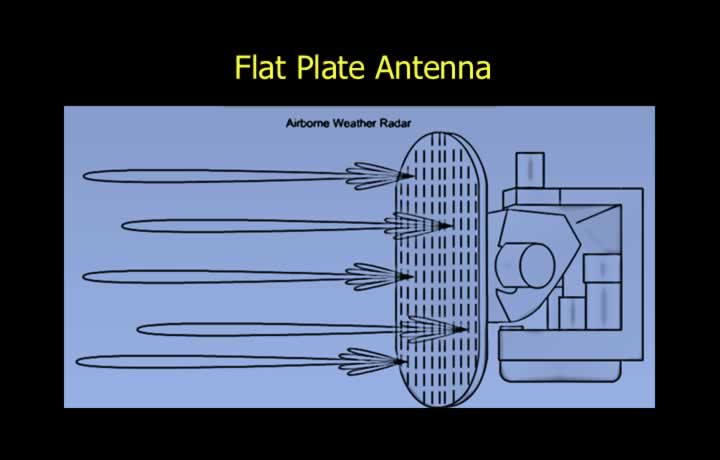
- Flat Plate Planar Slotted Array Antennas are commonly used in airborne radar systems.
- Flat plate antennas require less transmission energy.
- Transmission energy is increased by using multiple half-wavelength antenna elements.
- The elements are fed in phase through slots in a flat metal plate.
- Flat plate antennas produce narrow beams with reduced side lobes.
Minimum and Maximum Range of a Radar<>
Pulse Width (PW)
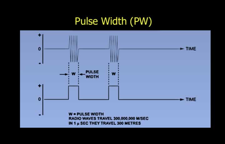
- Pulse Width or Pulse Length is the duration of transmission of a single radar pulse.
- Pulse width determines the minimum range of a radar.
- For a pulse width of 1 microsecond:
- If the one-way distance to the target is less than 150 m, the radar remains in transmission mode when the reflected pulse returns.
- The receiver cannot operate while transmitting.
- Therefore, the minimum one-way range is 150 m.
- Pulse width determines the minimum detectable range of primary radar.
Pulse Recurrence Frequency (PRF)
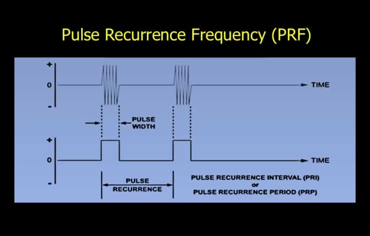
- Pulse Recurrence Interval (PRI) or Pulse Recurrence Period (PRP) is the time interval between the start of successive pulses.
- Pulse Recurrence Frequency (PRF) or Pulse Recurrence Rate (PRR) is the number of pulses transmitted per second.
Relationship Between PRI and PRF
- Pulse Recurrence Interval = 1 / Pulse Recurrence Frequency
Effect of PRF on Radar Range
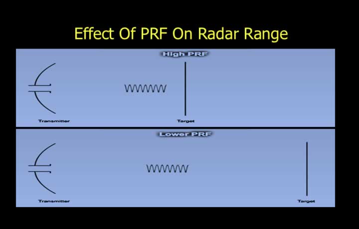
- PRF determines the maximum theoretical range of radar.
- A lower PRF provides a greater maximum range.
Radar Mile
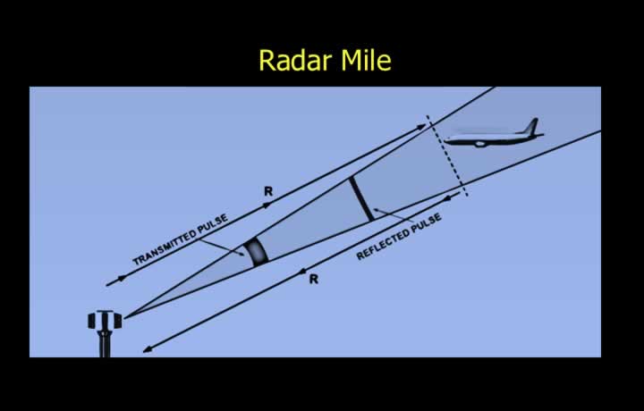
- Radar range calculations are based on slant range.
- Slant range is calculated using:
- Distance = Speed × Time
- The measured time is the time taken for the radar pulse to travel to the target and return.
- A radar mile is the time required for a radio wave to travel 1 NM and return.
- The value of one radar mile is approximately 12.36 microseconds.
Fly Back Time
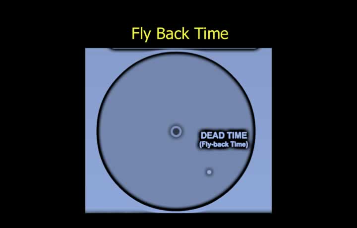
- Fly Back Time, also called dead time, is the time required for the display trace on a CRT screen to return to its starting position.
- Fly Back Time reduces the maximum practical radar range compared with the theoretical maximum range.
Factors Affecting Radar Range
- Pulse width determines the minimum range of radar.
- PRF determines the maximum range of radar.
- Transmitter power affects radar range.
- The inverse square law states that doubling the range requires four times the power.
- Since radar pulses travel to the target and return, doubling range requires approximately 16 times the transmitted power.
- Line-of-sight range is modified by atmospheric refraction.
- Target characteristics such as material, size, and aircraft shape affect radar detection.
- Mountain shadows and terrain obstacles may block radar waves.
- Rain attenuates radar waves, especially wavelengths below 4 cm.
- Super-refraction and sub-refraction may temporarily increase or decrease radar range.
Distortion in a Radar Picture
Beam Width Distortion
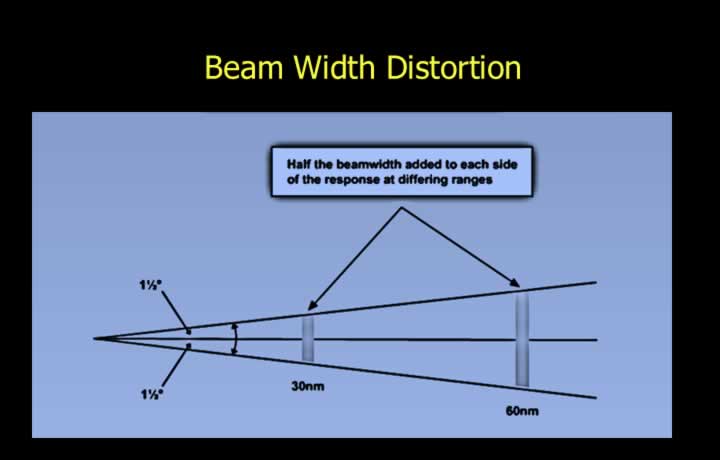
- Beam width distortion occurs due to the width of the radar beam.
- Half of the beam width is added on either side of the target.
- Beam width distortion increases with increasing range.
Pulse Length Distortion
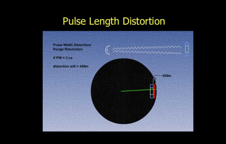
- Pulse length distortion occurs due to the length of the transmitted pulse.
- Half the pulse width is added to the rear of the target display.
- The displayed target size cannot be smaller than the distance represented by half the pulse width.
Spot Size Distortion
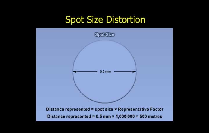
- Spot size distortion is caused by the display scale used in the cathode ray tube.
- The spot size is added around all sides of the displayed target.
- The represented distance equals:
- Spot Size × Representative Fraction
- Example: A 0.5 mm spot on a 1:1,000,000 scale represents approximately 500 meters.
Overall Radar Distortion
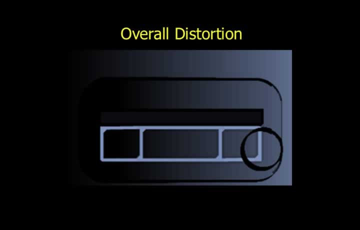
- Total radar picture distortion is the combined effect of:
- Beam width distortion.
- Pulse length distortion.
- Spot size distortion.
Techniques used in Modern Radar Systems
Radar Moving Target Indication (MTI)
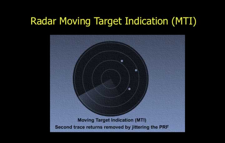
- Moving Target Indication (MTI) radar removes unwanted ground returns.
- It is designed to display only moving targets.
- MTI uses the Doppler principle to identify movement.
Jittering the PRF
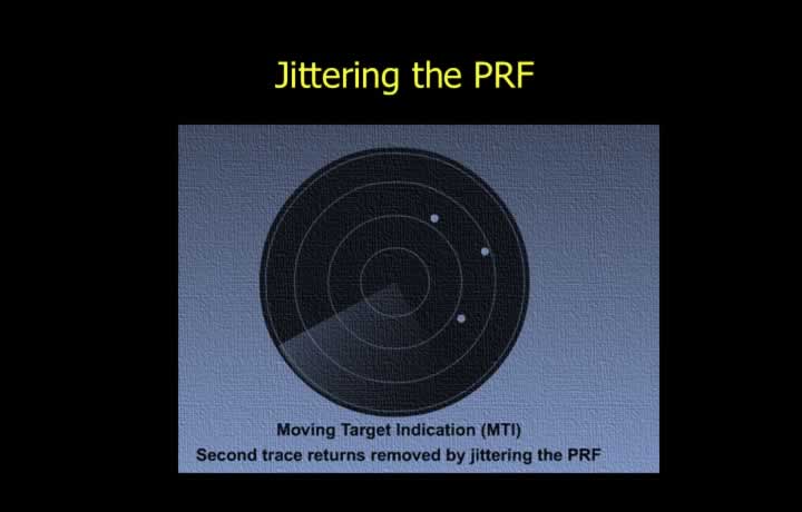
- PRF Jittering involves changing the PRF at random intervals.
- It prevents false targets caused by second trace returns.
- Second trace returns occur when echoes are received from targets beyond the maximum radar range.