
Microwave Landing System (MLS)
ILS (Instrument Landing System) uses radio beams to provide fixed landing guidance, while MLS (Microwave Landing System) uses microwave signals for more flexible guidance. ILS has limited approach paths, whereas MLS supports wider approach angles and curved approaches. MLS offers greater accuracy and is less affected by terrain and signal interference than ILS.
Introduction to MLS
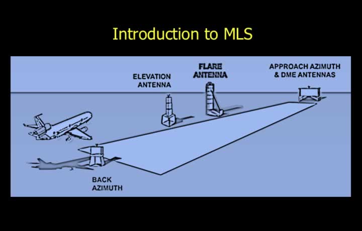
- The Microwave Landing System (MLS) consists of five integrated subsystems.
- Azimuth Guidance – Located beyond the stop end of the runway to provide lateral guidance.
- Elevation Guidance – Located on one side of the runway to provide vertical guidance.
- Distance Measuring Equipment (DME) – Co-located with the azimuth equipment to provide distance information.
- Missed Approach Guidance – Located ahead of the runway threshold to guide aircraft during missed approaches.
- Flare Guidance Subsystem – Assists aircraft during the flare and touchdown phase.
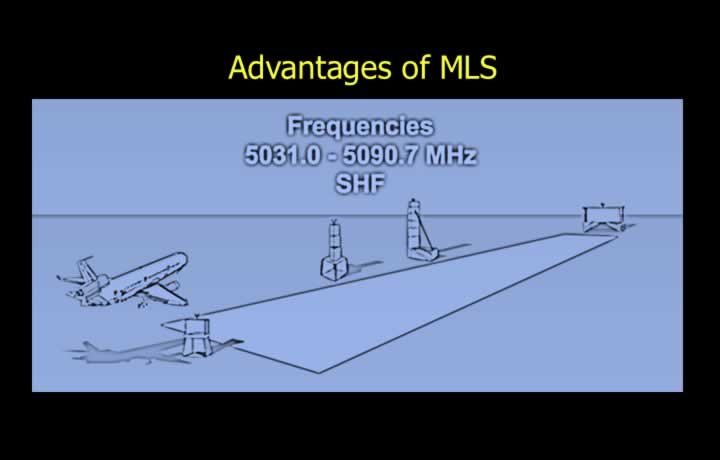
- MLS operates in the 5031.0 MHz to 5090.7 MHz frequency band (SHF).
- The emission designator is N0X, indicating a modulated carrier with digital data transmission.
Advantages of MLS
- Can be installed in mountainous or uneven terrain due to minimal site errors.
- Unaffected by interference from civilian FM radio broadcasts.
- Provides up to 200 operating channels in the SHF band.
- Supports flexible approach paths, reducing arrival delays.
- More economical to install because DME is integrated with the system.
- Flexible glide paths accommodate all aircraft types, including helicopters.
- Can transmit supplementary information such as weather and runway conditions.
Principle of MLS
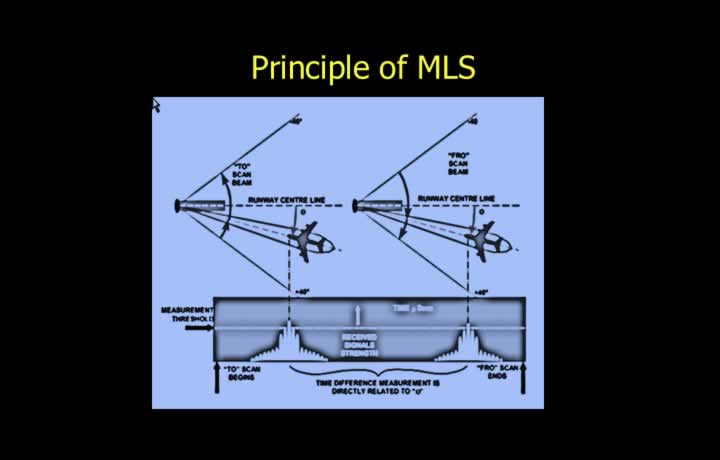
- MLS operates using the Time Referenced Scanning Beam (TRSB) principle.
- The Azimuth Scanning Beam scans from left to right at approximately 13.5 scans per second.
- The Elevation Scanning Beam scans from top to bottom at approximately 40.5 scans per second.
- Azimuth and Elevation scans determine the aircraft’s horizontal and vertical position.
- The aircraft calculates its position by measuring the time difference between the TO and FROM scanning beams.
- MLS uses Time Division Multiplexing (TDM) to allow all subsystems to share the same frequency.
- Distance from the runway threshold is provided by a frequency-paired precision DME.
Coverage of MLS
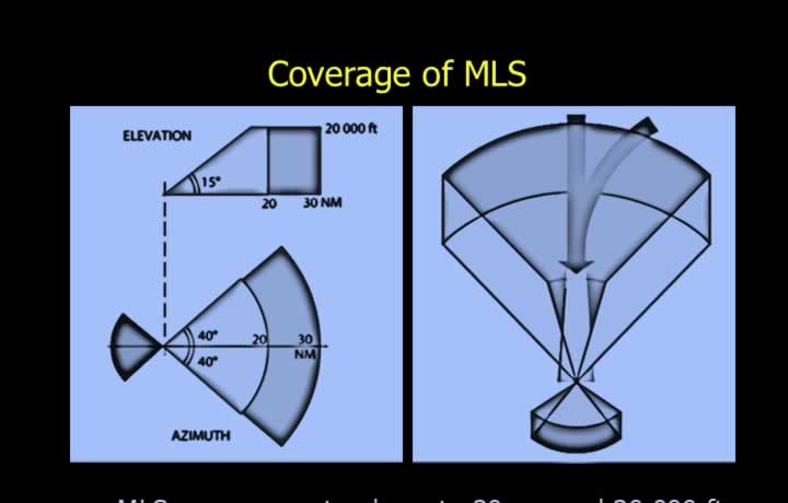
- Forward coverage extends up to 20 NM and 20,000 ft.
- Azimuth coverage extends up to 40° on either side of the runway centreline.
- Elevation coverage ranges from 0.9° to 20° above the horizontal.
- Offset approaches can provide guidance even when the aircraft is approximately 2 NM from touchdown.
- Back beam coverage extends up to 10 NM and 10,000 ft.
- Back beam azimuth coverage extends up to 20° on either side of the runway.
- Back beam elevation coverage ranges from 0.9° to 15° above the horizontal.
- Back beam guidance may be used for missed approaches and departures.
Accuracy of MLS
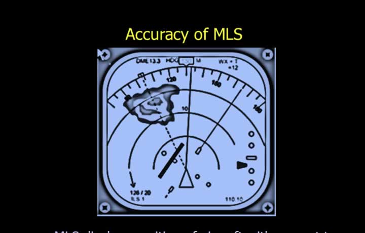
- MLS provides precise aircraft position relative to the selected approach path.
- Displayed information includes course, height, and distance.
- The MLS approach reference datum is located 50 ft above the runway threshold.
- ICAO recommends an accuracy of approximately 13.5 ft at the reference datum.
- The maximum permissible error at the maximum range of 20 NM is approximately 27 ft.
- Horizontal position error normally does not exceed 20 ft.
- Vertical position error is limited to approximately 2 ft at the Aerodrome Reference Datum.
- The maximum glide path error is approximately 0.2° on a standard 3° glide path.