Direction Measurement using Very High Frequency Omni-Directional Radio Range (VOR)
VOR (VHF Omnidirectional Range) is a radio navigation system that provides aircraft with accurate directional guidance. It helps pilots determine their bearing (radial) from a VOR ground station. VOR is widely used for en-route navigation and instrument flight procedures.
Introduction to VOR
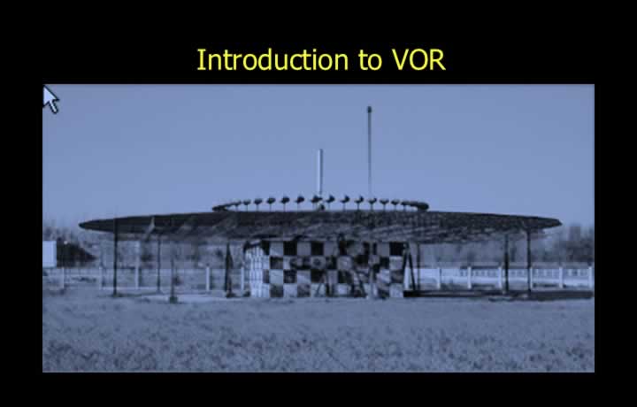
- Very High Frequency Omni-Directional Radio Range (VOR) is a short-range radio navigation aid approved by ICAO.
- VOR is largely free from static interference and night effect, making it suitable for both day and night operations.
- VOR determines aircraft bearing using the principle of phase comparison.
- The station simultaneously transmits a Reference Signal and a Variable Signal.
- The phase difference between these signals determines the aircraft’s radial.
- Aircraft equipment consists of a VHF dipole antenna and a VOR receiver.
- VOR information is displayed on the Radio Magnetic Indicator (RMI) and Course Deviation Indicator (CDI).
VOR Transmission
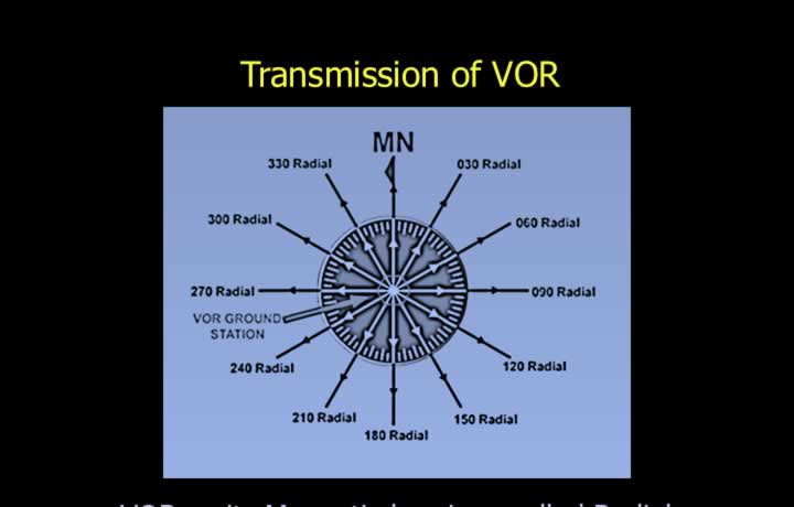
- VOR transmits magnetic bearings known as radials.
- There are 360 radials, each separated by 1°.
- VOR transmits horizontally polarised VHF radio waves.
- Operating frequencies range from 108.00 MHz to 117.95 MHz.
- VOR frequencies use even first decimal digits (e.g., 108.60 MHz).
- Each station broadcasts a unique three-letter Morse code identification or station name.
- The identification is transmitted at least seven times per minute.
- ATIS or a continuous tone may replace the Morse identification.
Emission Designator
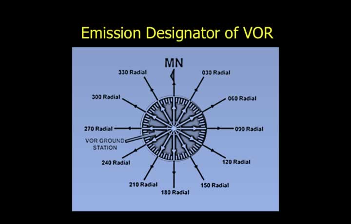
- The emission designator for VOR is A9W.
- A – Double-sideband amplitude modulation.
- 9 – Composite modulation system.
- W – Telemetry or transmission of measured information.
Principle of VOR
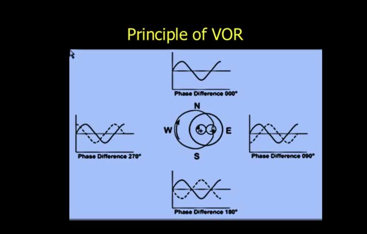
- VOR determines bearing by comparing the phase of the Reference and Variable signals.
- The combined radiation pattern forms a Limacon.
- The Reference Signal is a constant-phase, omnidirectional 30 Hz frequency-modulated signal.
- The Variable Signal is a 30 Hz amplitude-modulated signal whose phase changes as the Limacon rotates.
- The airborne receiver measures the phase difference between the two signals.
- At Magnetic North, the Reference and Variable signals are in phase.
- The measured phase difference corresponds to the aircraft’s magnetic bearing (radial).
Doppler VOR (DVOR)
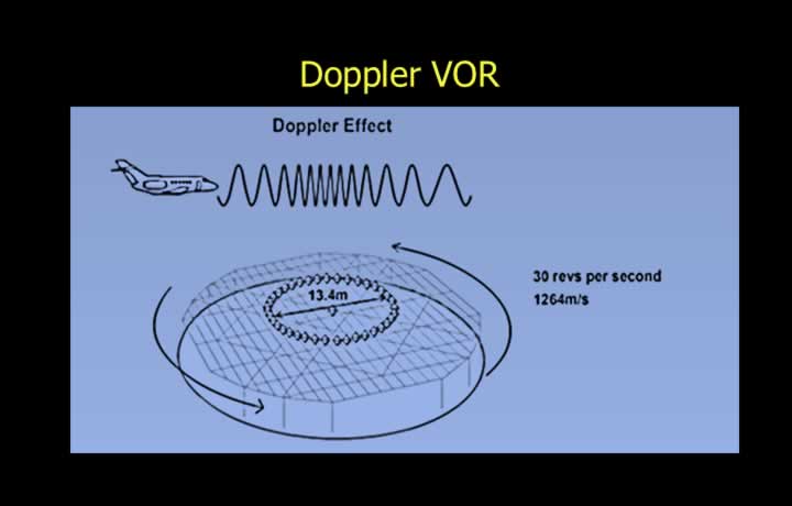
- Doppler VOR minimises site errors caused by uneven terrain and ground reflections.
- A DVOR uses a circular array approximately 13.4 m in diameter with 48 transmitting elements.
- The Variable Signal is frequency modulated to create the Doppler effect.
- This method produces less interference than conventional amplitude modulation.
- An electronically rotating antenna produces the required phase shift.
- The antenna rotates electronically at approximately 30 revolutions per second.
- The airborne receiver measures phase differences to determine the selected radial.
Range and Accuracy of VOR
Designated Operational Coverage (DOC)
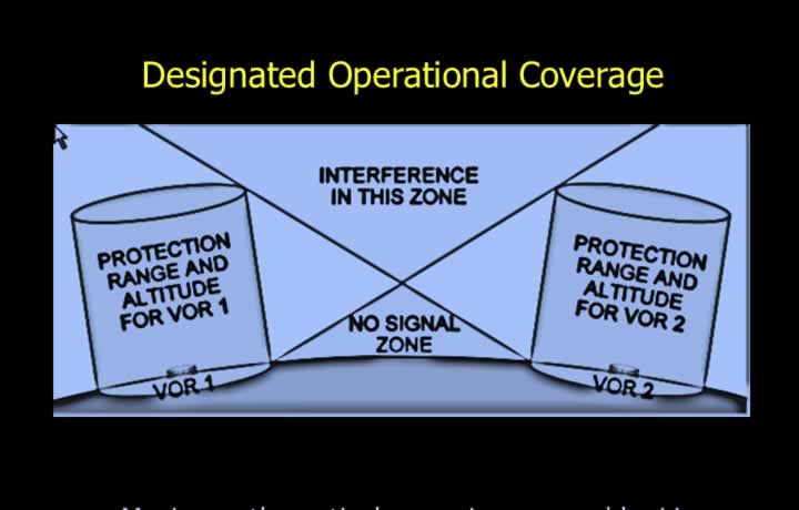
- The maximum theoretical range is determined by the line-of-sight principle.
- Actual range also depends on transmitter power.
- The inverse square law governs transmission power requirements.
- Designated Operational Coverage (DOC) is the protected service area around a VOR.
- DOC prevents interference from nearby VOR stations operating on the same frequency.
- DOC is expressed as Distance/Altitude.
- DOC 50/25 indicates service up to 50 NM and 2,500 ft.
- Different DOC values exist for Terminal, Low Altitude, and High Altitude VORs.
Accuracy of VOR
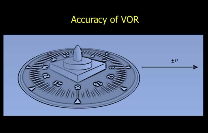
- Overall VOR accuracy depends on both ground station and airborne equipment.
- Proper site selection limits beacon error to less than 1°.
- Doppler VOR significantly reduces site errors.
- Airborne receiver error is normally limited to less than 3°.
- Total system error is generally limited to less than 5°.
VOR Monitoring Equipment
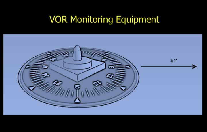
- The station identification is automatically removed whenever system errors exceed permissible limits.
- Conditions that trigger shutdown include:
- Radial transmission error greater than 1°.
- Transmitter power loss greater than 15%.
- Failure of the ground monitoring equipment.
- The aircraft indicator displays a red or yellow warning flag whenever VOR information becomes unreliable.
Cone of Ambiguity (Cone of Confusion)
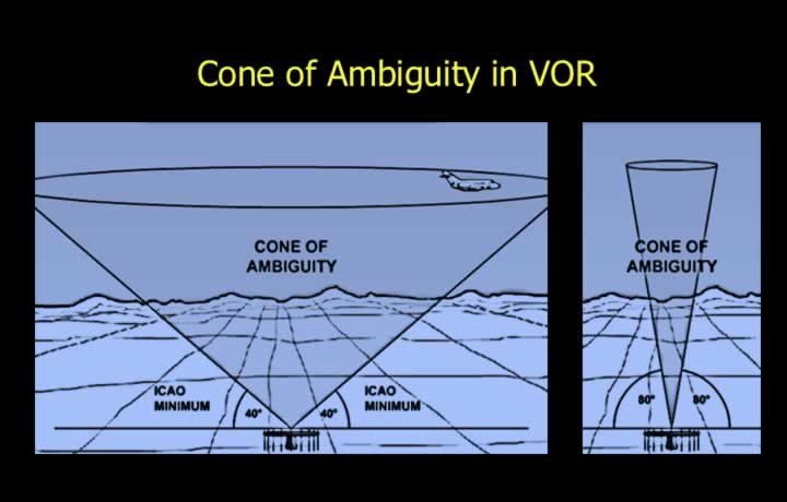
- The airspace directly above a VOR station is known as the Cone of Ambiguity or Cone of Confusion.
- Within this region, VOR indications fluctuate and become unreliable.
- ICAO limits the cone to approximately 40° elevation.
- In practice, unreliable indications rarely extend beyond about 80° elevation.
Airway Navigation Using VOR
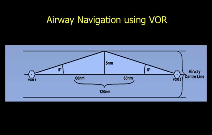
- Typical VOR system accuracy is approximately ±5°.
- Standard airway width is 10 NM (5 NM on either side of the centreline).
- According to the 1-in-60 rule, a 5° error corresponds to approximately 5 NM at 60 NM.
- Airways normally have VOR stations spaced approximately 120 NM apart.
- This ensures aircraft remain within acceptable navigation accuracy.
Types of VOR
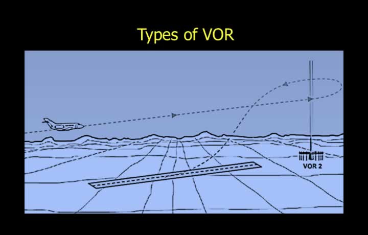
- CVOR – Conventional VOR used along airways.
- BVOR – Broadcast VOR providing weather and airfield information.
- DVOR – Doppler VOR designed to minimize site errors.
- TVOR – Terminal VOR with reduced power for airport operations.
- VOT – Test VOR used to verify airborne VOR equipment.
- During a VOT test, airborne equipment should indicate 360° ±4°.
- VORTAC – A co-located VOR and TACAN station.
- DBVORTAC – Combination of DVOR, BVOR, and VORTAC facilities.
Cockpit Indications of VOR on RMI, CDI and HSI
Radio Magnetic Indicator (RMI)
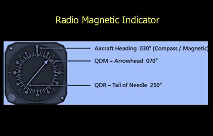
- The Radio Magnetic Indicator (RMI) displays magnetic bearings from both NDB and VOR.
- The head of the pointer indicates QDM (bearing to the station).
- The tail of the pointer indicates QDR (bearing from the station).
- The ADF pointer converts relative bearings into magnetic bearings.
- The VOR pointer displays magnetic radials directly.
Course Deviation Indicator (CDI)
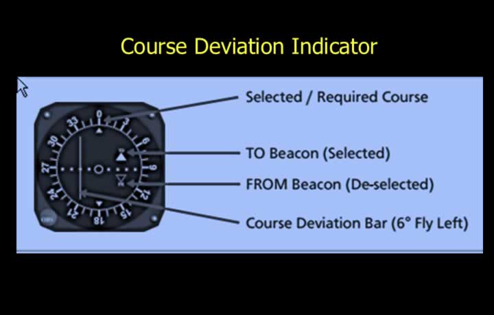
- The Course Deviation Indicator (CDI), also called the Omni Bearing Indicator (OBI), displays deviation from a selected radial.
- The desired course is selected using the Omni Bearing Selector (OBS).
- The CDI is used to intercept and maintain a selected VOR radial.
- The deviation bar always points toward the selected course.
- The TO/FROM indicator shows whether the selected course leads toward or away from the station.
- In VOR mode, the CDI provides approximately 10° of full-scale deflection on each side.
- On a five-dot indicator, each dot represents approximately 2°.
- The CDI provides left/right course guidance without considering aircraft heading.
Horizontal Situation Indicator (HSI)
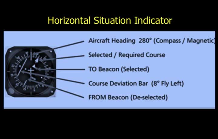
- The Horizontal Situation Indicator (HSI) combines heading and navigation information into a single display.
- It displays the selected magnetic track or radial.
- It indicates deviation from the selected VOR course.
- It simultaneously displays aircraft heading and required heading.
- The HSI provides intuitive left/right steering commands that account for aircraft heading.
Electronic Horizontal Situation Indicator (EHSI)
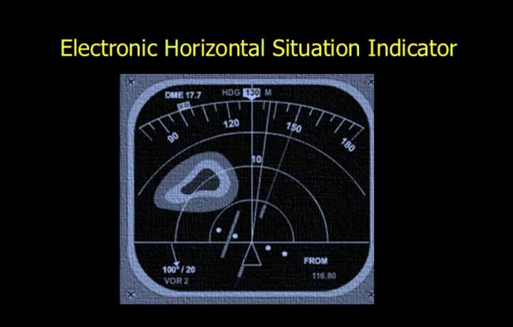
- The Electronic Horizontal Situation Indicator (EHSI) provides additional navigation information.
- Displays terrain and weather information from the Airborne Weather Radar.
- Displays terrain proximity warnings from the Terrain Collision Avoidance System (TCAS/TAWS, depending on installation).
- Displays distance information from Distance Measuring Equipment (DME).