
Non-Directional Beacon (NDB) & Automatic Direction Finder (ADF)
NDB (Non-Directional Beacon) is a ground-based radio transmitter used for aircraft navigation. It provides a reference signal that helps pilots determine the direction of the station using an Automatic Direction Finder (ADF). NDB is used for en-route navigation and instrument approach procedures.
Introduction to NDB
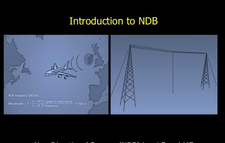
- A Non-Directional Beacon (NDB) is a ground-based radio transmitter operating in the LF and MF frequency bands.
- NDB transmits a vertically polarised interrupted carrier-wave signal.
- The transmission is radiated uniformly through 360°.
- Operating frequencies range from 190 kHz to 1750 kHz.
- NDB antennas are generally large T-shaped aerials because of the long wavelengths involved.
- Typical emission designators are NON-A1A and NON-A2A.
- The operational range varies from approximately 25 NM to 500 NM, depending on the purpose of the beacon.
- Each NDB continuously transmits a unique three-letter Morse code identification.
Principle of ADF
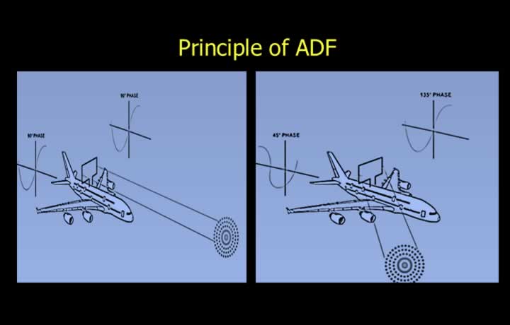
- The Automatic Direction Finder (ADF) uses NDB transmissions for navigation.
- ADF operates within the frequency range of 190–1750 kHz.
- It determines the direction of an NDB using the loop antenna principle.
- The loop antenna consists of two vertical elements that receive the radio signal.
- Signals arriving simultaneously produce no phase difference.
- Equal phase results in zero current flowing through the loop circuit.
- Zero current indicates that the beacon lies perpendicular to the loop antenna.
- The measured current is processed to determine the bearing of the station.
Null Position in ADF
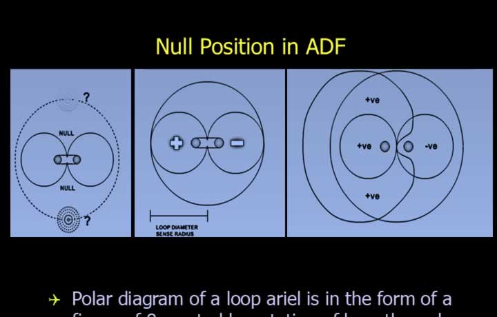
- The polar diagram of a loop antenna is shaped like a figure of eight.
- The null position occurs when the NDB is either directly ahead of or behind the aircraft.
- A sense antenna resolves the front/back ambiguity.
- Combining the loop and sense antennas produces a cardioid (heart-shaped) radiation pattern.
- This cardioid pattern has only one null position.
- The front/back ambiguity of the loop antenna is therefore eliminated.
- The polarity of the sense antenna may be switched periodically to improve accuracy.
Components of an ADF
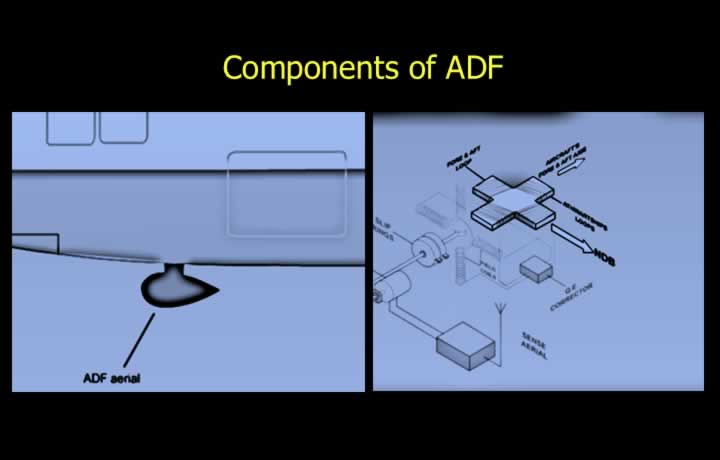
- The loop and sense antennas are mounted together inside a teardrop-shaped housing.
- The antenna assembly is usually installed on the underside of the aircraft fuselage.
- Modern ADF systems use two fixed loop antennas mounted at right angles.
- The antennas are connected to a goniometer that measures the bearing.
- A search coil detects the null position.
- A motor rotates the search coil until the null position is reached.
- The position of the search coil determines the relative bearing displayed.
ADF Control Panel
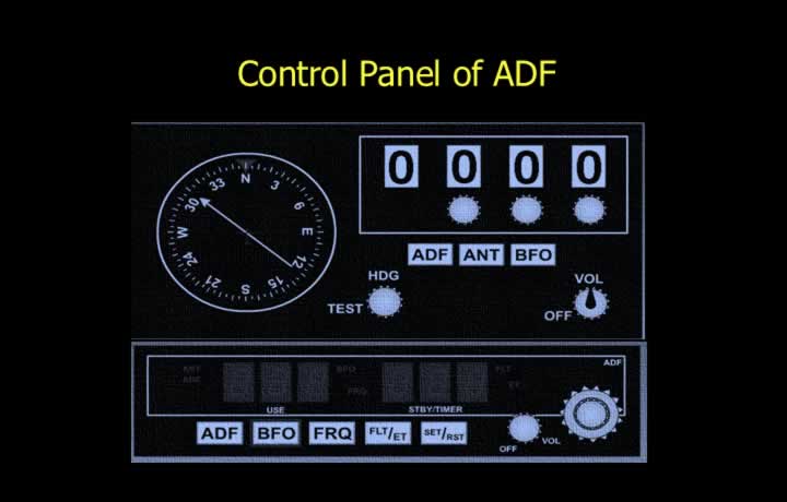
- The ADF is controlled from a cockpit control panel.
- Digital control panels normally provide active and standby frequency selection.
- The frequency selector is used to tune the desired NDB.
- The ANT (Antenna) mode is used to listen to the Morse code identification.
- Bearings should be ignored while operating in ANT mode because the loop antenna is disconnected.
- The Beat Frequency Oscillator (BFO) enables reception of NON-A1A transmissions.
- Bearings should also be ignored while BFO mode is selected.
- The TEST button checks the serviceability of the indicator.
- A serviceable indicator needle moves approximately 90° during the test.
Beat Frequency Oscillator (BFO)
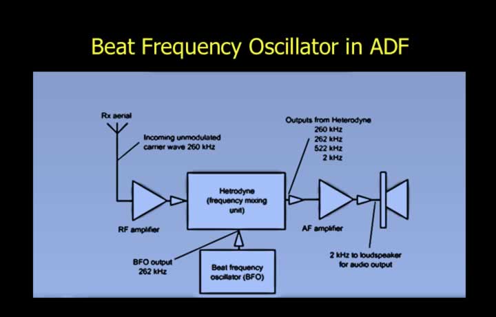
- Every NDB continuously transmits a unique three-letter Morse identification.
- NON-A1A transmissions require the BFO to be selected ON for audio reception.
- The heterodyne circuit inside the BFO generates an audible beat frequency.
- The beat frequency is produced by mixing the received carrier with an internally generated frequency.
- BFO should be selected during tuning, identification, and signal monitoring.
- NON-A2A transmissions can be heard without using the BFO.
- Amplitude modulation used by A2A transmissions reduces their effective range.
- The BFO switch may also be labelled TONE or VOICE.
ADF indications inside the Cockpit using RBI and RMI
Relative Bearing Indicator (RBI)
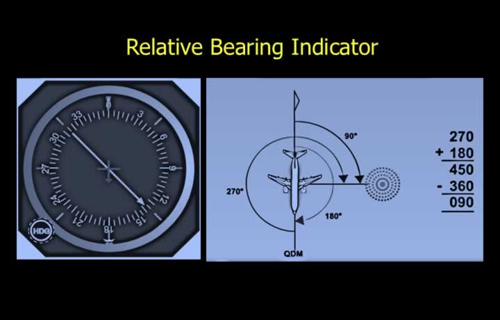
- The Relative Bearing Indicator (RBI) displays the position of the NDB relative to the aircraft’s longitudinal axis.
- QDM is the magnetic bearing to the station.
- QDM = Aircraft Heading + Relative Bearing.
- If the total exceeds 360°, subtract 360°.
- QDR is the magnetic bearing from the station.
- If QDM is less than 180°, add 180°.
- If QDM is greater than 180°, subtract 180°.
- A movable compass card allows the pilot to manually set aircraft heading.
- The head of the needle indicates QDM, while the tail indicates QDR.
Radio Magnetic Indicator (RMI)
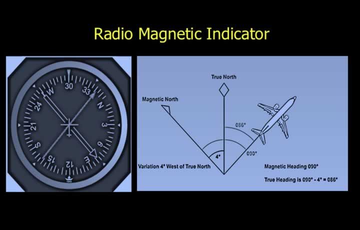
- The Radio Magnetic Indicator (RMI) displays magnetic bearings directly on a rotating compass card.
- The rotating compass card continuously shows the aircraft heading.
- The head of the needle indicates QDM.
- The tail of the needle indicates QDR.
- Many RMIs contain two independent needles for two NDBs, two VORs, or one of each.
- True bearings can also be obtained after applying variation and deviation corrections.
Inherent Errors of ADF
Terrain Effect
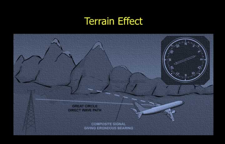
- Terrain effect is caused by reflected radio waves from hills and mountains.
- Flying at higher altitudes in mountainous terrain reduces terrain effect.
Static Interference
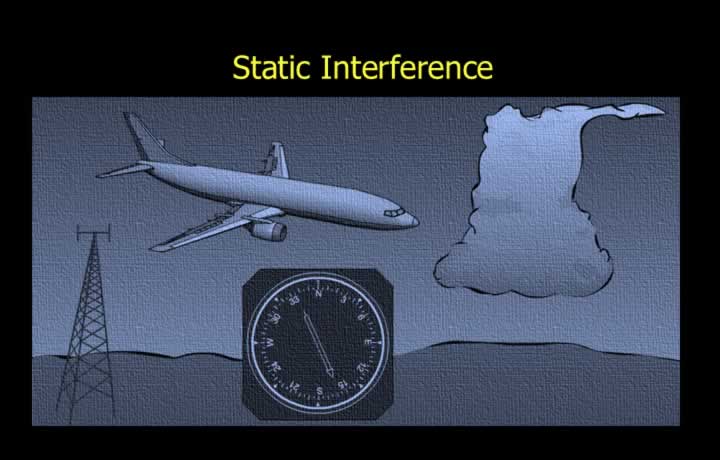
- Static interference is caused by electrical discharges from thunderstorms and charged clouds.
- ADF indications should be treated with caution during thunderstorm activity.
Quadrantal Error
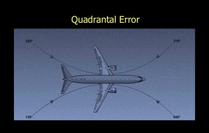
- Quadrantal error is caused by distortion of radio waves by the aircraft structure.
- The greatest error occurs on quadrantal headings.
- Modern electronic compensation systems significantly reduce quadrantal error.
Cone of Silence
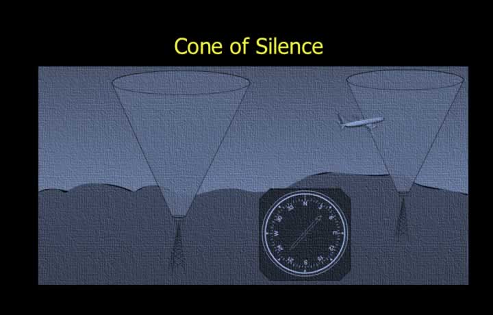
- The cone of silence is located directly above the NDB where the ADF needle fluctuates rapidly and becomes unreliable.
Dip Error
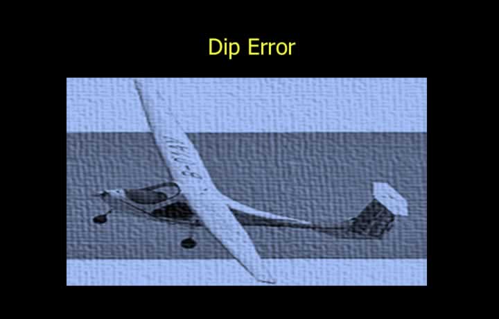
- Dip error causes the ADF needle to indicate toward the side to which the loop antenna is tilted.
Coastal Refraction
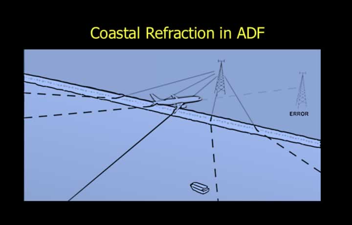
- Coastal refraction occurs when radio waves cross the boundary between land and sea.
- Radio waves travel faster over seawater than over land.
- The waves bend toward the slower medium (land).
- The effect decreases as frequency increases.
- NDBs located near coastlines generally operate on higher frequencies to minimize this error.
- The angle at which the coastline is crossed also affects the magnitude of the error.
- Minimum coastal refraction occurs when crossing the coastline at right angles.
Night Effect
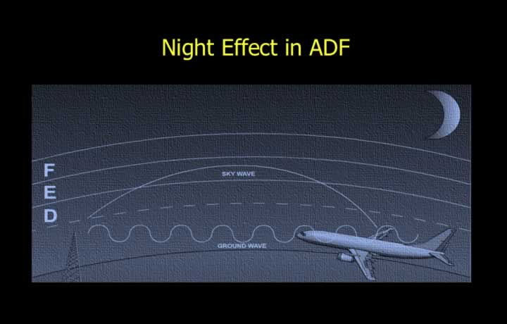
- Night effect reduces the accuracy of ADF bearings after sunset.
- During daylight, the D-layer absorbs most sky waves.
- After sunset, the D-layer disappears, allowing sky waves to return to Earth.
- The returned sky waves interfere with the surface waves from the same NDB.
- Sky waves usually arrive out of phase and with different polarization.
- Horizontally polarised sky waves induce unwanted currents in the loop antenna.
- ADF indications often wander during dawn and dusk.
Station Interference
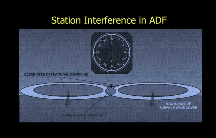
- Station interference occurs when two or more NDBs operate on similar frequencies.
- Designated Operational Coverage (DOC) ensures accurate bearings during daytime operations.
- DOC is achieved through careful frequency allocation.
- DOC limitations do not apply at night because of night effect.
- ADF systems provide no automatic failure warning.
- Positive identification of the NDB using its Morse code is essential before navigation.
Range and Accuracy of ADF
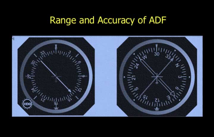
- ADF range depends on both transmitter characteristics and environmental conditions.
- Transmitter power, operating frequency, and emission type affect the usable range.
- Mountainous terrain and precipitation reduce the effective operating range.
- High-quality receivers improve reception and usable range.
- A minimum signal-to-noise ratio of 3:1 is required for reliable ADF operation.
- Within the Designated Operational Coverage (DOC), daytime bearing accuracy is typically about ±5°.