
Properties of Electro-Magnetic Waves – Basics of EM Waves used in Radio Navigation
Electromagnetic (EM) waves are waves that carry energy from one place to another. They do not need a material medium, so they can travel through air, water, and even the vacuum of space. EM waves include radio waves, microwaves, infrared, visible light, ultraviolet, X-rays, and gamma rays. They are widely used in communication, medicine, navigation, and aviation.
Electrical and Magnetic Field
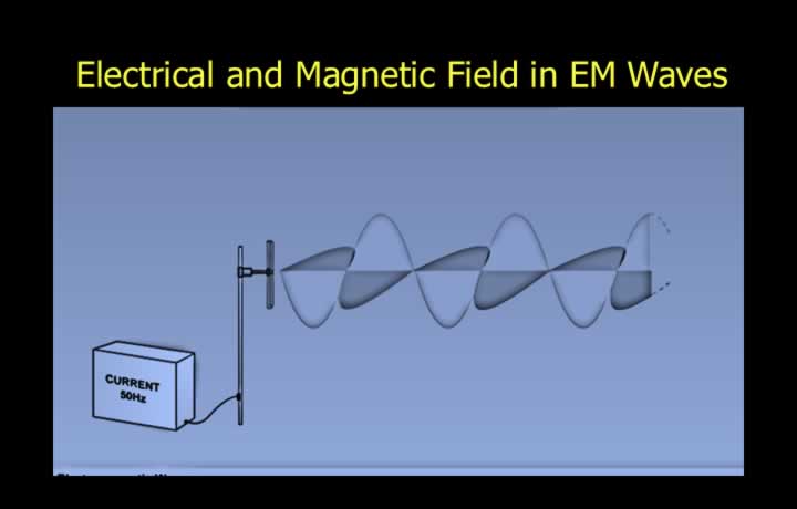
- Radio aids in aviation use Electro-Magnetic (EM) Waves.
- EM waves are created by the movement of alternating current (AC) in a wire.
- Alternating current creates a magnetic field perpendicular to the electric field.
- EM radiation is transmitted through air if the wire is connected to an aerial.
- EM radiation consists of electrical and magnetic components.
- The electrical field lies in the same plane as the aerial.
- The magnetic field is perpendicular to the electrical field.
Electro-Magnetic Spectrum
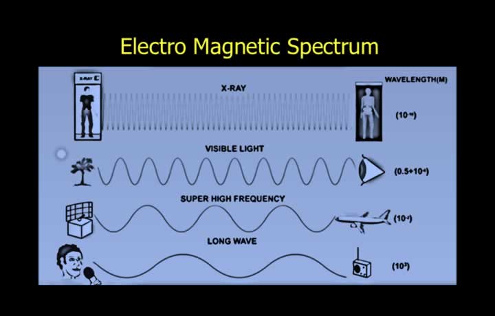
- EM waves can travel through a vacuum and have a wide spectrum.
- Spectrums differ in wavelength, frequency, and energy.
- Visible light is the only part of the EM spectrum visible to the naked eye.
- X-rays have higher frequencies and shorter wavelengths.
- Long-wave audio signals have lower frequencies and longer wavelengths.
Short Wave and Long Wave
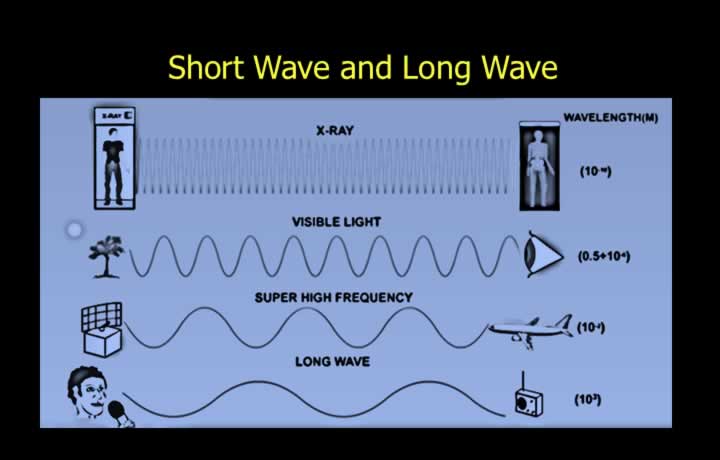
- Short waves have high levels of energy and are therefore more harmful to the body.
- EM waves travel at the speed of light in a vacuum regardless of their spectrum.
- Speed of light in a vacuum is approximately 3 × 10⁸ m/s (about 186,000 miles/s).
Polarisation of Electromagnetic waves
Horizontal and Vertical Polarisation
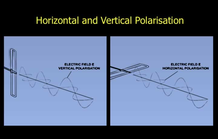
- Electrical and magnetic components of EM waves are perpendicular to each other.
- Polarisation is the plane of the electrical component, which carries the information.
- Vertical and horizontal aerials transmit vertically and horizontally polarised waves respectively.
- Vertically polarised waves can only be received by a vertical aerial.
- Horizontally polarised waves can only be received by a horizontal aerial.
Circular Polarisation
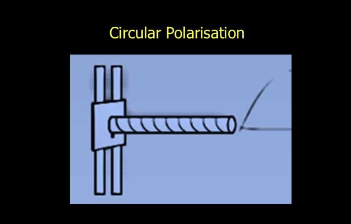
- Circularly polarised waves are created by a helical antenna.
- Circular polarisation can be received by various types of antennas.
- Used when polarisation changes during transmission.
- Reduces rain clutter but requires higher transmitter power.
Relationship between Time-Period, Wavelength and Speed of EM Waves
Speed of EM Wave
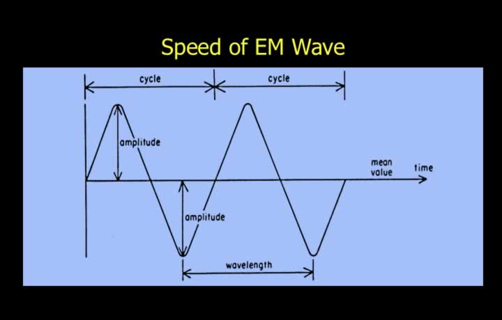
- EM radiation is transmitted as a sinusoidal (sine) waveform.
- The frequency of the wave is the same as the alternating current producing it.
- The speed of an EM wave is equal to the speed of light.
- The speed is maximum in a vacuum.
- Radio waves travel faster over water than over land.
Time Period of EM Wave
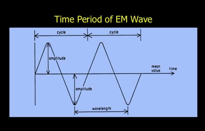
- One cycle is one complete waveform.
- A cycle extends from the mean position to maximum, minimum, and back to the mean position.
- The time period is the time required to complete one cycle.
- Time period is usually expressed in microseconds (10-6 seconds).
Frequency and Wavelength
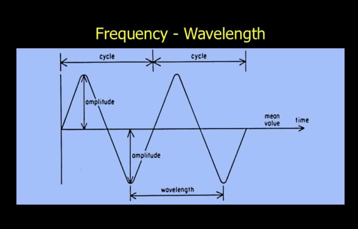
- Amplitude is the maximum displacement from the mean position.
- Frequency (Hz) is the number of cycles completed each second.
- Wavelength (m) is the distance travelled during one cycle.
- Frequency and wavelength are inversely proportional.
Speed – Frequency – Wavelength
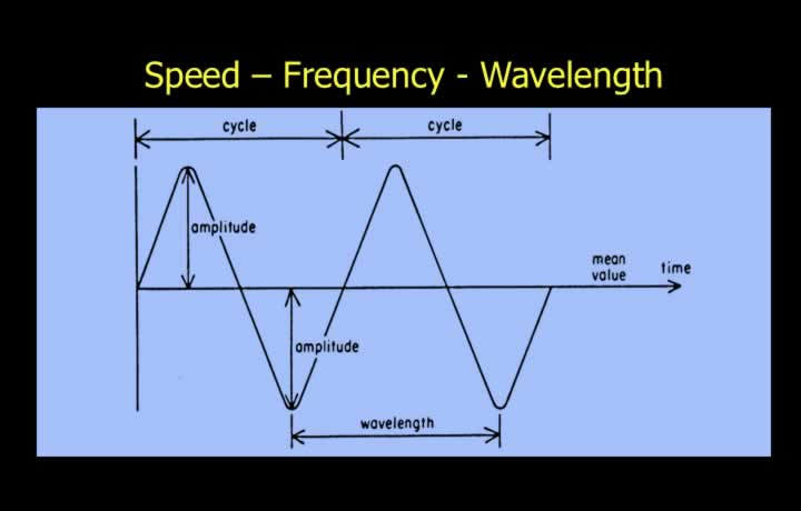
- Speed is the distance travelled by an EM wave in one second.
- Wave speed is the product of wavelength and frequency.
- Speed = Wavelength × Frequency
- In a vacuum, the speed equals the speed of light.
Formula
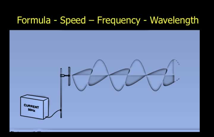
Speed = Frequency × Wavelength
Frequency = Speed of Light ÷ Wavelength
Wavelength = Speed of Light ÷ Frequency
Units of Frequency Measurement
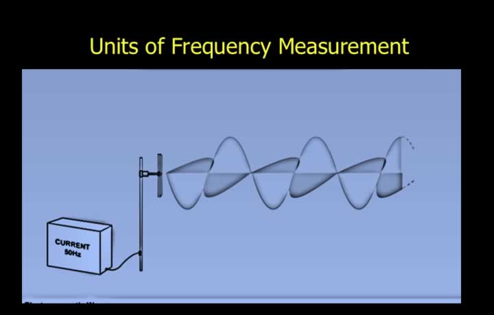
- 1 Hertz (Hz) = 1 cycle per second.
- 1 Kilohertz (kHz) = 1,000 Hz = 103 Hz.
- 1 Megahertz (MHz) = 1,000 kHz = 106 Hz.
- 1 Gigahertz (GHz) = 1,000 MHz = 109 Hz.
Classification of Radio Waves
Radio Wave Frequency Bands
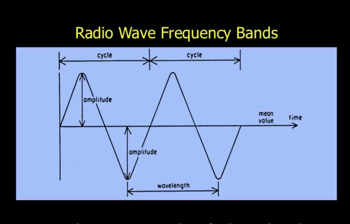
| Band | Frequency | Wavelength |
|---|---|---|
| VLF | 3–30 kHz | 100–10 km |
| LF | 30–300 kHz | 10–1 km |
| MF | 300–3000 kHz | 1000–100 m |
| HF | 3–30 MHz | 100–10 m |
| VHF | 30–300 MHz | 10–1 m |
| UHF | 300–3000 MHz | 100–10 cm |
| SHF | 3–30 GHz | 10–1 cm |
| EHF | 30–300 GHz | 10–1 mm |
Power and Phase of Radio Waves
Phase Difference Between EM Waves
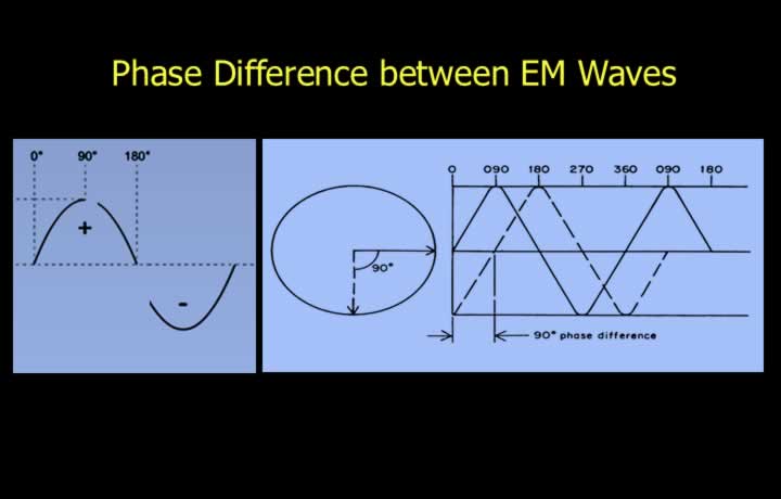
- Phase is a defined position on a sine waveform.
- It is expressed from 0° to 360°.
- Phase difference is the difference in phase between two waves.
- It is determined by comparing waveforms.
- Phase comparison is only possible between waves of the same frequency.
- This principle is used in some radio navigation equipment.
Power of Radio Wave
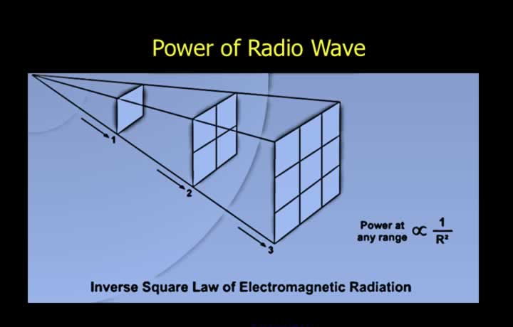
- Radio wave power decreases as distance from the transmitter increases.
- The inverse square law governs electromagnetic radiation.
- Available power is inversely proportional to the square of the distance.
- To double the range, transmitter power must be increased fourfold.
Polar Diagram
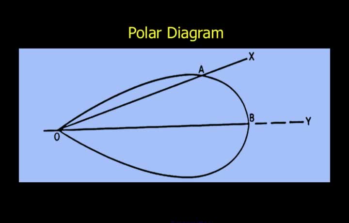
- A polar diagram joins points of equal signal strength.
- The antenna shape determines the polar diagram.
- For transmitters, it joins points receiving half the transmitted power.
- Polar diagrams are used for both transmitters and receivers.
- Receiver polar diagrams connect points receiving half the received power.
Attenuation – Loss of Power during Transmission
Surface Attenuation
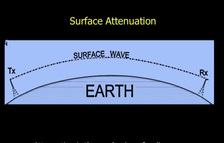
- Attenuation is the weakening of radio waves during transmission.
- It follows the inverse square law.
- Surface attenuation results from absorption by the Earth’s surface.
- Vertically polarised waves experience less surface attenuation.
- Horizontally polarised waves experience greater attenuation.
- Surface attenuation increases with frequency.
- Very Low Frequency (VLF) bands are used for submarine communication.
Factors Affecting Signals
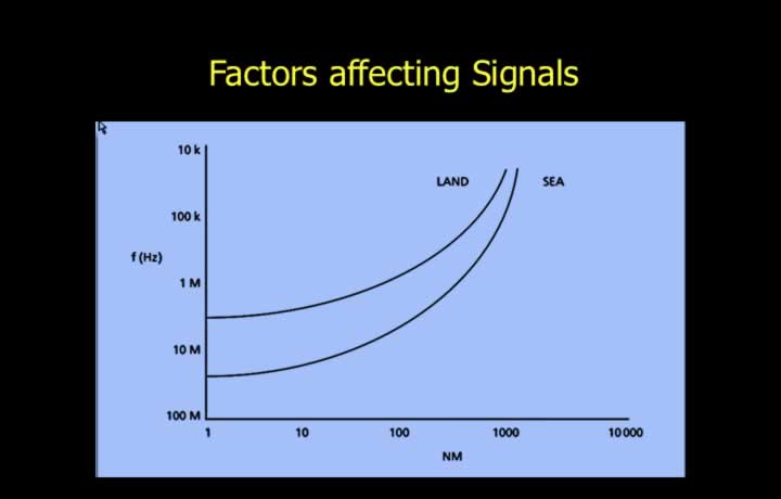
- Surface attenuation is greater over land than over sea.
- Land range is proportional to three times the square root of power.
- Sea range is proportional to twice the square root of transmitter power.
- Reflection attenuation is caused by buildings and hills.
- Taller aerials reduce reflection attenuation.
Fading of Signals
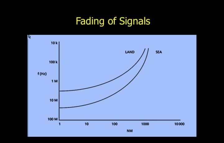
- Fading causes fluctuations in signal strength.
- This is known as waxing and waning.
- Fading occurs when out-of-phase signals arrive via different paths.
Atmospheric Attenuation
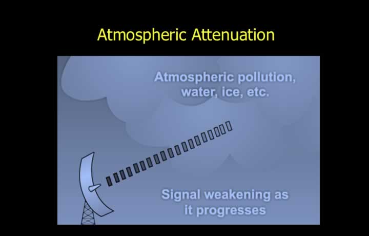
- Atmospheric attenuation weakens radio waves.
- It is caused by atmospheric absorption and static interference.
- Absorption results from particles in the atmosphere.
- Higher frequencies suffer greater atmospheric absorption.
- Frequencies around 5 GHz are heavily affected.
- The wavelength at these frequencies is similar to the size of water droplets.
Static Interference
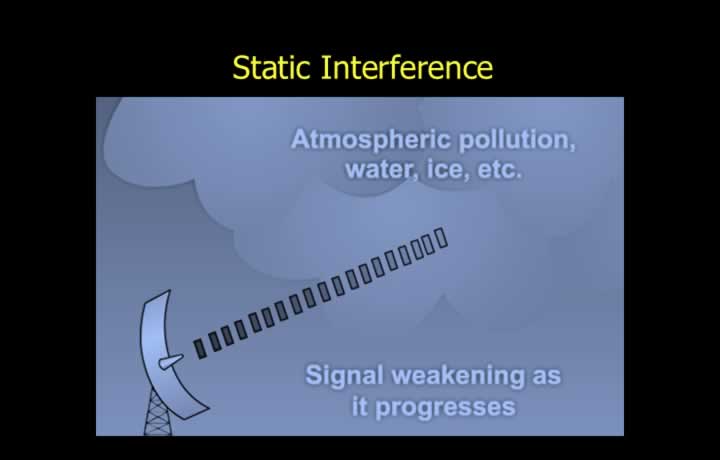
- Static interference is caused by electrical charges in the atmosphere.
- It increases during rain, thunderstorms, and solar activity.
- Lower frequencies experience greater static interference.
- Electronic circuits can also generate static noise.
Signal-to-Noise Ratio (SNR)
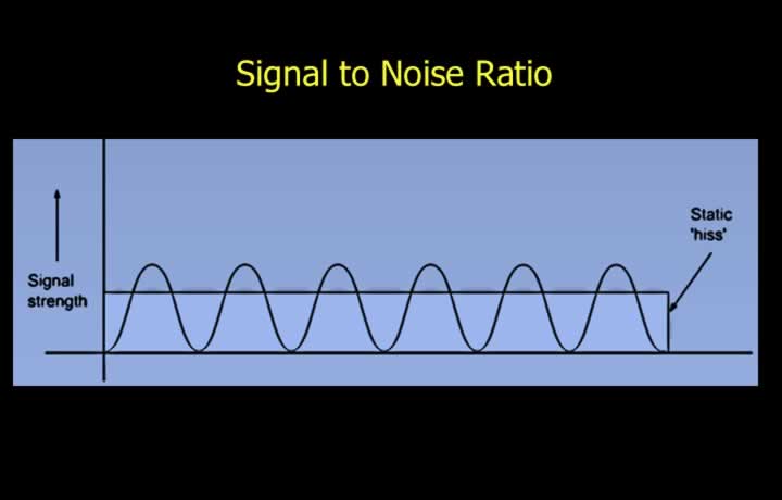
- SNR is the ratio of signal strength to noise, expressed in decibels (dB).
- It can be improved by increasing transmission power.
- Doubling range requires four times the transmitter power.
- Receiver sensitivity can also be improved by reducing internal noise.
- This enables reception of weaker signals.
Change in Direction of Radio Waves during Transmission
Diffraction and Refraction
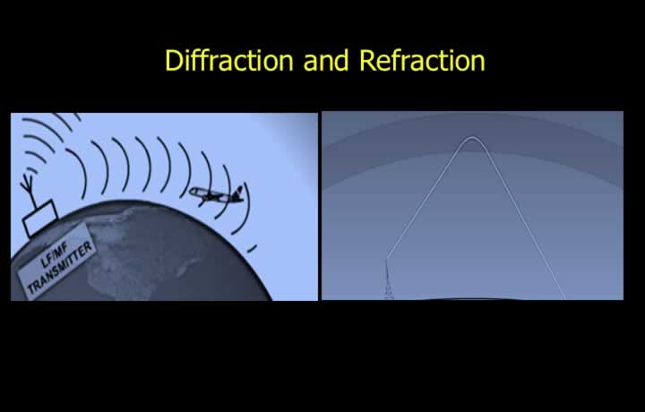
- Diffraction is the bending of radio waves around the Earth’s surface.
- Lower frequencies (VLF, LF, HF) experience greater diffraction.
- Refraction is the bending of waves due to changes in propagation speed caused by changes in medium density.
Ionospheric Refraction
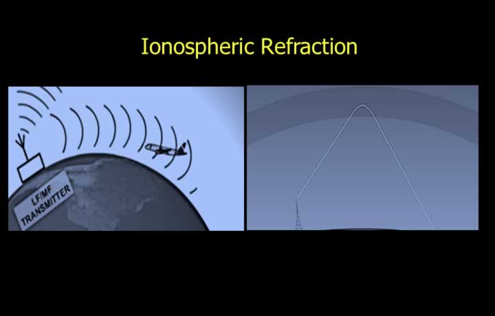
- Occurs when radio waves slow down in the ionosphere.
- Some refracted waves return to Earth.
- Ionospheric refraction decreases as frequency increases.
Super Refraction
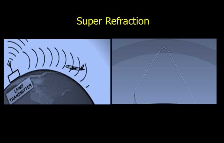
- Normally affects only lower frequencies.
- Special atmospheric conditions may refract higher frequencies.
- Caused by high-pressure systems.
- Also caused by warm air flowing over a cold surface.
Sub Refraction
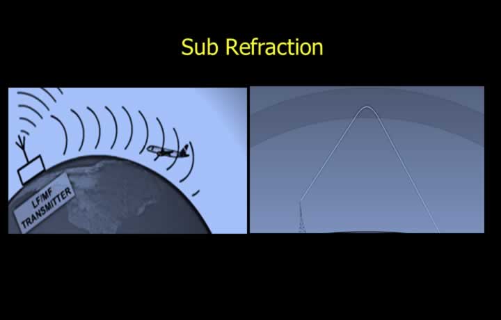
- Caused by atmospheric conditions.
- Associated with low-pressure systems.
- Occurs when cold air flows over a warm surface.
- Super and sub-refraction can unexpectedly increase VHF range.
Coastal Refraction
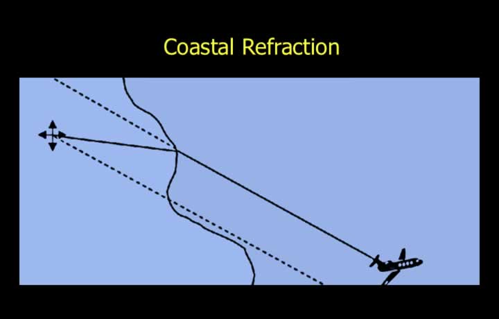
- Coastal refraction affects radio aids located near coastlines.
- Occurs when radio waves cross the land-sea boundary.
- Radio waves travel faster over sea than over land.
- They bend toward the slower medium (land).
- Coastal refraction is less significant at higher frequencies.
- Non-Directional Beacons (NDBs) near coastlines often use higher frequencies to minimize this effect.