Factors affecting Landing Performance
Landing performance is the aircraft’s ability to land safely and come to a complete stop within the available runway distance. It includes the approach, touchdown, braking and stopping distance required. Landing performance depends on factors such as aircraft weight, runway condition, wind, weather and braking effectiveness.
Landing Segment
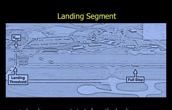
- The landing segment begins at the runway threshold and ends when the aircraft comes to a complete stop.
- The standard landing screen height is 50 ft above the runway threshold.
- All categories of aircraft use the same landing screen height.
- Flight manual landing performance data is valid only if the aircraft crosses the threshold at the correct landing reference speed (Vref).
- For Class A aircraft, Vref is the higher of:
- 1.23 × Vsr (stall reference speed).
- Vmcl (minimum control speed in the landing configuration).
- For aircraft other than Class A, Vref = 1.3 × Vso, where Vso is the stall speed in the landing configuration.
Landing Distance Required
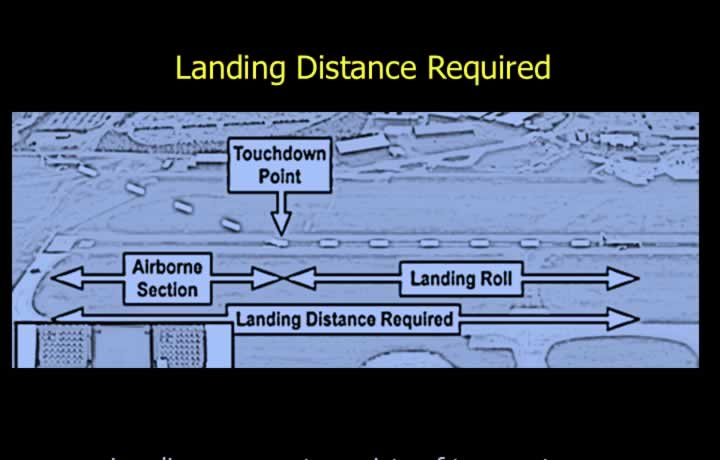
- The landing segment consists of:
- Airborne section.
- Landing roll.
- The airborne section extends from the 50 ft screen height to the touchdown point.
- Touchdown normally occurs approximately 1,000 ft from the runway threshold.
- The landing roll extends from touchdown until the aircraft comes to a complete stop.
- The landing flare is also known as the round-out.
- During the flare, thrust is reduced to idle and the nose is gently raised.
- After touchdown, braking is assisted by spoilers and reverse thrust.
- Landing Distance Required (LDR) is the total distance of the airborne section plus the landing roll.
Forces During Landing
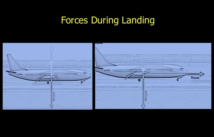
- Weight acts downward through the aircraft’s centre of gravity.
- In flight, lift balances weight.
- After touchdown, the runway reaction supports the aircraft weight.
- Landing weight is generally lower because fuel has been consumed during flight.
- Lift becomes undesirable during the landing roll and must be reduced quickly.
- Reducing forward thrust also helps reduce lift.
Reduction of Lift Force
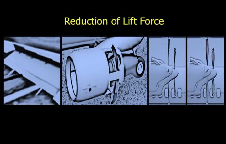
- Lift is reduced using spoilers and reverse thrust in jet aircraft.
- Spoilers destroy the wing’s aerodynamic shape, rapidly reducing lift.
- Reverse thrust slows the aircraft, reducing lift as speed decreases.
- In jet aircraft, reverse thrust is activated by a safety microswitch on the landing gear.
- The engine redirects airflow forward to create reverse thrust.
- In propeller aircraft, blade pitch is reversed to produce reverse thrust.
Reverse Thrust in Jet Aircraft
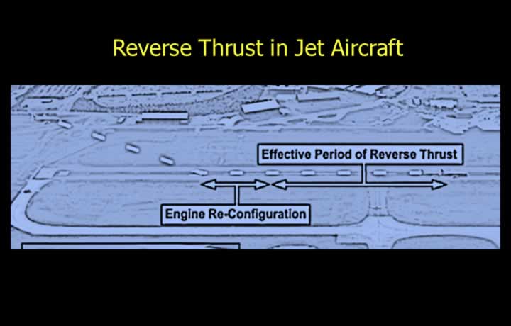
- Reverse thrust becomes available only after the landing gear safety switch is activated.
- Jet engine reversers require a short deployment time.
- Reverse thrust must be cancelled before reaching low taxi speeds.
- It is therefore effective only during the initial portion of the landing roll.
Reverse Thrust in Propeller Aircraft
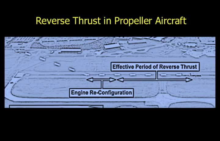
- Propeller aircraft use reverse blade pitch to generate reverse thrust.
- Reverse pitch can be selected almost immediately after touchdown.
- It remains effective until the aircraft comes to a complete stop.
- Propeller reverse thrust provides greater braking effectiveness than jet reverse thrust.
- Reverse thrust is normally not included in certified landing performance calculations.
- Actual landing distances are therefore usually shorter than calculated values.
Aerodynamic Drag
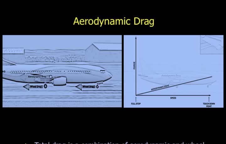
- Total drag is the combination of aerodynamic drag and wheel drag.
- Aerodynamic drag consists of induced drag and parasite drag.
- Induced drag depends on lift and angle of attack.
- In flight, higher angle of attack produces greater lift and induced drag.
- After touchdown, lift reduces significantly and induced drag decreases.
- Parasite drag depends on aircraft shape and configuration.
- Flaps and slats increase parasite drag in flight.
- After touchdown, spoilers and speed brakes further increase parasite drag.
- Aerodynamic drag is highest immediately after touchdown and decreases as speed reduces.
- Landing flaps increase drag and reduce landing distance.
- During a go-around, flaps should be retracted progressively as recommended.
Wheel Drag
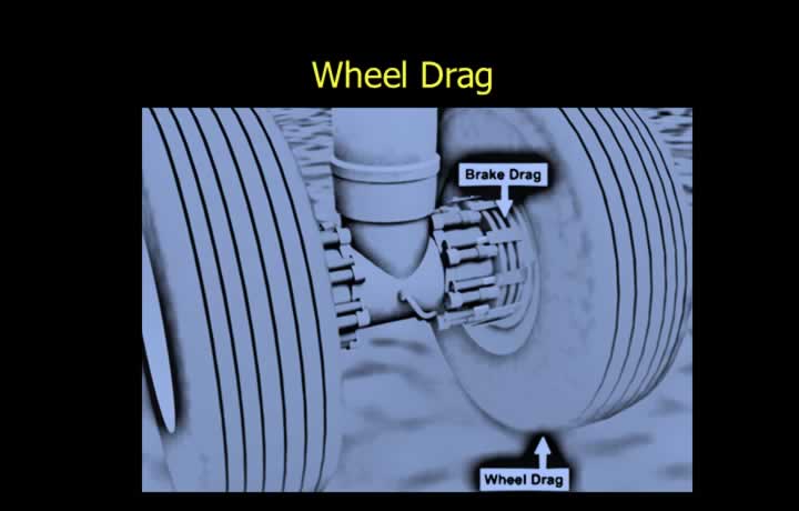
- Wheel drag is created by friction between the tires and the runway surface.
- As lift decreases during the landing roll, more aircraft weight is transferred onto the wheels.
- This increases wheel drag.
Brake Drag
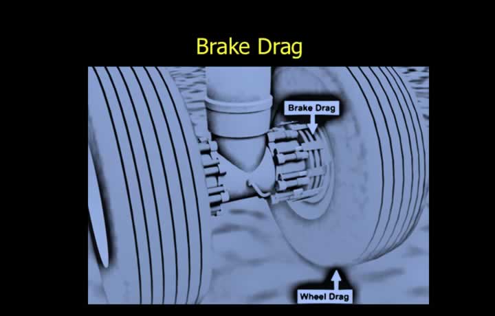
- Brake drag is generated by friction between brake discs and brake pads.
- It provides the greatest braking force during landing.
- Effective braking depends on sufficient tire-to-runway friction.
- Immediately after touchdown, braking effectiveness is reduced because wheel loading is lower.
- Brake effectiveness increases as lift is destroyed.
- Rapid lift dump is essential for achieving short landing distances.
- Auto-brake systems combined with anti-skid systems provide optimum braking performance.
Effect of Total Drag
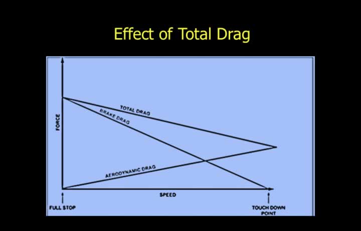
- Aerodynamic drag decreases while brake drag increases during the landing roll.
- Immediately after touchdown, aerodynamic drag provides most of the deceleration.
- At lower speeds (below approximately 70% of landing speed), braking becomes the primary retarding force.
- Total decelerating force increases during the landing roll.
- Brake failure can significantly increase landing distance.
Landing Distance Required
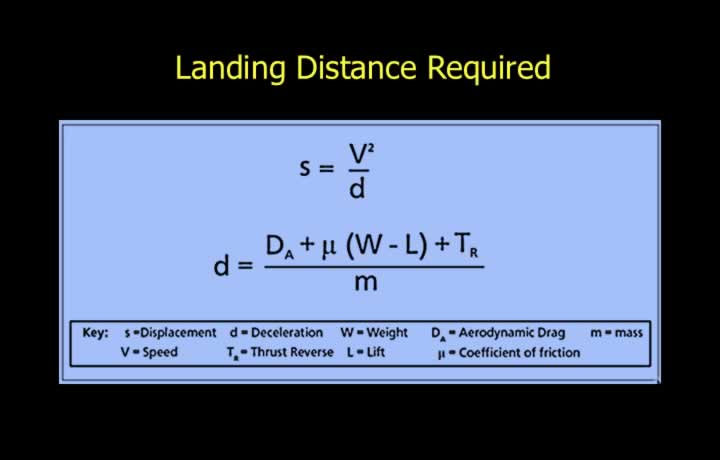
- Landing distance depends on landing speed and aircraft deceleration.
- Deceleration depends on braking force and aircraft mass.
- Deceleration Force = Aerodynamic Drag + Braking Force + Reverse Thrust
Factors Affecting Landing Distance
Effect of Mass on Landing Distance
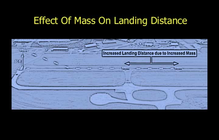
- Landing distance increases as aircraft mass increases.
- Greater mass produces higher momentum and reduces deceleration.
- Heavier aircraft also approach at higher landing speeds.
- Wheel and brake loading increases with weight.
- The overall result is a longer landing distance.
Effect of Air Density on Landing Distance
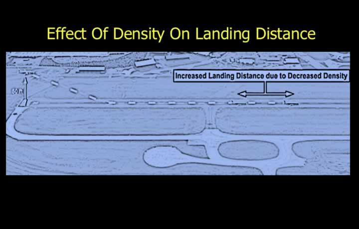
- Landing distance increases as air density decreases.
- Reduced density decreases reverse thrust effectiveness.
- True Airspeed (TAS) is higher for the same Indicated Airspeed (IAS).
- Higher TAS results in higher touchdown speed.
- High, hot and humid conditions therefore reduce landing performance.
Effect of Wind on Landing Distance
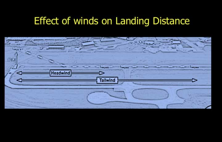
- Headwinds reduce landing distance.
- Tailwinds increase landing distance.
- Headwinds reduce ground speed during touchdown.
- Tailwinds increase ground speed.
- Performance calculations normally assume:
- 50% of the reported headwind.
- 150% of the reported tailwind.
- No allowance is made for crosswinds; published crosswind limits must not be exceeded.
Effect of Runway Slope on Landing Distance
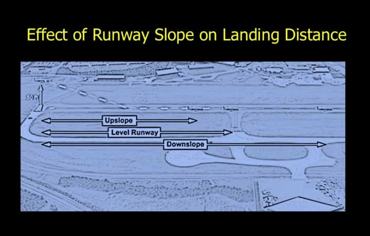
- On an upslope runway, a component of aircraft weight assists braking.
- Landing distance is therefore reduced.
- On a downslope runway, a component of weight opposes braking.
- Landing distance increases.
- A useful rule of thumb is a 5% change in landing distance for every 1% runway slope.
- For safety, upslope benefits are generally ignored in performance calculations.
Effect of Runway Surface on Landing Distance
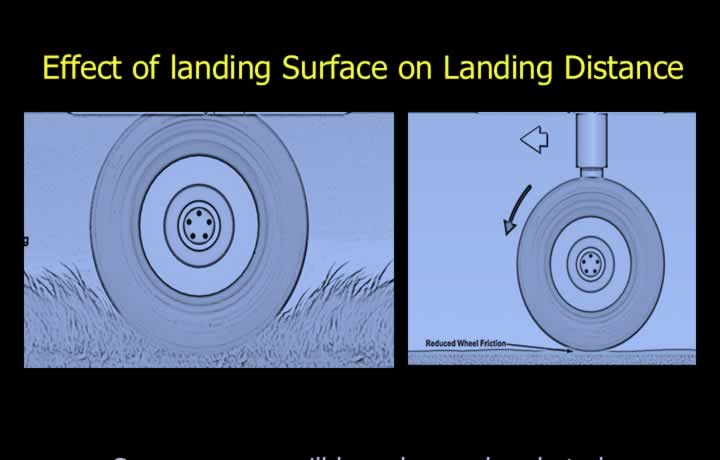
- Grass runways reduce braking effectiveness and may increase landing distance by up to 15%.
- Snow, slush and other contaminants reduce tire friction.
- Reverse thrust becomes especially valuable on contaminated runways.
- Damp runways contain moisture but are not reflective.
- Wet or contaminated runways may increase landing distance by approximately 50%.
- Wet runways are reflective with less than 3 mm of standing water.
- Contaminated runways contain more than 3 mm of standing water, snow or slush.
Types of Aquaplaning or Hydroplaning
Dynamic Aquaplaning (Hydroplaning)
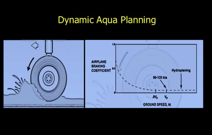
- Dynamic aquaplaning occurs when tires ride on a layer of standing water.
- Braking becomes ineffective because the tires lose contact with the runway.
- The approximate hydroplaning speed is:
- VP (knots) = 9 × √(Tire Pressure in PSI)
- Grooved tires and crowned (convex) runway surfaces help reduce dynamic aquaplaning.
- Runway grooving also improves water drainage and braking effectiveness.
Viscous Aquaplaning
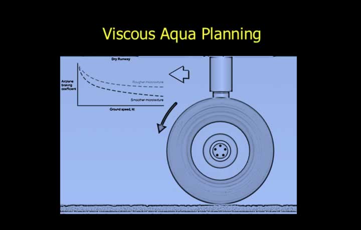
- Viscous aquaplaning occurs on smooth runway surfaces covered by a thin film of water.
- The water acts as a lubricant between the tire and runway.
- It can occur even at relatively low speeds.
- Runway micro-texture helps prevent viscous aquaplaning.
Reverted Rubber Aquaplaning
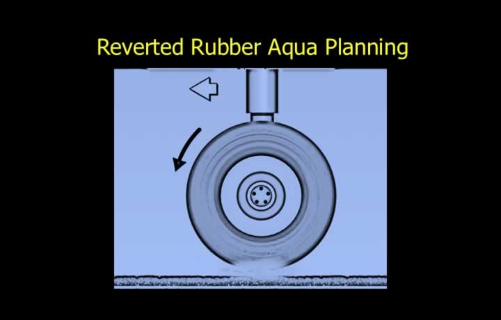
- Reverted rubber aquaplaning occurs when locked wheels generate excessive heat.
- The heat converts water into steam beneath the tire.
- The steam lifts the tire off the runway surface.
- Anti-skid braking systems are designed to prevent this form of aquaplaning.